Control Diagram
NOTE:
A
= Hardwired connection; F
= RF Transmission; N
= Medium speed CAN bus; O
LIN bus; W
= LF Transmission; AH
= Serial Communications Link
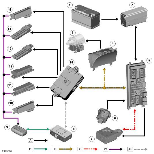
| Item Number | Description |
|---|---|
| 1 | Battery |
| 2 | EJB (engine junction box) |
| 3 | Steering column lock |
| 4 | Instrument cluster |
| 5 | CJB |
| 6 | Start/Stop Switch |
| 7 | Immobilizer antenna unit |
| 8 | Radio frequency receiver |
| 9 | Smart Key |
| 10 | Interior Antenna - roof lining |
| 11 | Interior Antenna - roof lining |
| 12 | Interior Antenna - luggage compartment |
| 13 | Interior Antenna - luggage compartment |
| 14 | Interior Antenna - front compartment |
| 15 | Interior Antenna - front compartment |
| 16 | KVM (Keyless Vehicle Module) |