Upper Arm: Installation
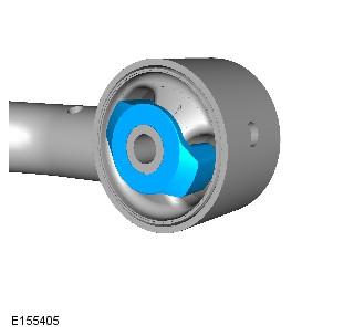
- Check the bumpstop inserts are correctly installed.
- Install the upper arm.
- Fit the bolts but do not fully tighten at this stage.
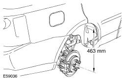
- Set the height, between the center of the halfshaft end and the edge of the fender trim, to 463 mm (18.23").
- Support with an axle stand.
- Connect the upper arm and wheel knuckle.
- Align the bolt to the marks made previously.
- Tighten the bolt to 133 Nm (98 lb.ft).
- Tighten the upper arm front bolt to 175 Nm (129 lb.ft).
- Tighten the upper arm rear bolt to 275 Nm (203 lb.ft).
- Secure the wheel speed sensor lead.
- Secure the brake pad wear indicator sensor lead.
- Connect the height sensor link.
- Install the brake tube.
- Tighten the brake tube unions to 18 Nm (13 lb.ft).
- Bleed the brake system. Refer to Component Bleeding .
- Install the wheel and tire.
- Tighten the wheel nuts to 140 Nm (103 lb.ft).
- Carry out the wheel alignment procedure.
CAUTION:
Make sure that bumpstop inserts are fitted on both sides of the front bushing prior to installation of the arm. Failure to follow this instruction may result in damage to the bushing.
NOTE:
Bumpstop inserts are installed to both sides of the bushing.
CAUTION:
Make sure the ball joint seal is not damaged. A damaged seal will lead to the premature failure of the joint.