Instrument Cluster: Operation
| Item Number | Description |
|---|---|
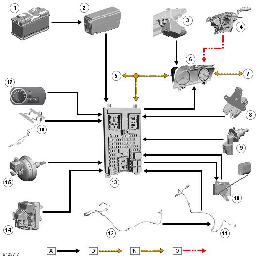
| 1 | Battery |
| 2 | Battery Junction Box (BJB) |
| 3 | Steering-column-lock module |
| 4 | Clockspring |
| 5 | Medium-speed CAN bus connection to other vehicle systems |
| 6 | Instrument cluster |
| 7 | High-speed CAN bus connection to other vehicle systems |
| 8 | Tailgate ajar switch |
| 9 | Engine coolant level sensor |
| 10 | Fuel level sensor |
| 11 | Front brake-pad wear sensor |
| 12 | Rear brake-pad wear sensor |
| 13 | Central Junction Box (CJB) |
| 14 | Washer fluid level sensor |
| 15 | Brake fluid level sensor |
| 16 | Safety belt - occupant detection pressure sensor |
| 17 | Exterior light control switch |
The instrument cluster receives a permanent fused supply from the Battery Junction Box (BJB).
The cluster is connected to other vehicle systems and control modules via the:
- medium speed CAN bus,
- high speed CAN bus and
- LIN bus connections
However, some vehicle sensors are hardwired directly to the instrument cluster.
The steering lock control module is connected to a hardwired connection to the instrument cluster. Security information from other control modules is passed via the network buses and when the conditions are correct the instrument cluster instructs the steering lock control module to unlock the steering column.
The clockspring is connected to the instrument cluster on a LIN bus connection. The LIN bus passes driver selections made on the steering wheel mounted switches to the instrument cluster for processing and transmission to other control modules.