Control Diagram
NOTE:
A
= Hardwired; D
= High speed CAN Bus
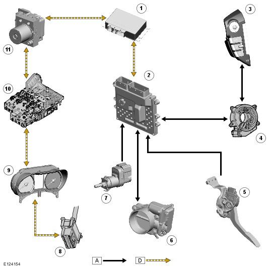
| Item Number | Description |
|---|---|
| 1 | Transfer box control module |
| 2 | Engine Control Module (ECM) |
| 3 | Left Hand (LH) steering wheel speed control switches |
| 4 | Clock spring |
| 5 | Accelerator Pedal Position (APP) sensor |
| 6 | Electric throttle |
| 7 | Brake switch |
| 8 | Diagnostic socket |
| 9 | Instrument cluster |
| 10 | Transmission Control Module (TCM) |
| 11 | Anti-lock Brake System (ABS) module |