Brake Master Cylinder And Reservoir: Reservoir
The reservoir is installed on top of the master cylinder to provide a supply of brake fluid for the primary and secondary circuits of the brake system. On manual gearbox models, the reservoir also provides a supply of brake fluid for the clutch.
Two straps, integrated onto the sides of the reservoir, engage with lugs on the master cylinder to secure the reservoir in position. Two outlet spigots on the underside of the reservoir locate in seals installed in the inlet ports of the master cylinder. An outlet spigot is installed on the left side of the reservoir for the clutch hydraulic circuit, if required. On automatic gearbox models, the clutch outlet spigot is sealed with a cap, formed during manufacture of the reservoir, which is only removed if the reservoir is installed on a manual gearbox model.
The reservoir is internally divided to isolate the circuits from each other at low fluid levels, and so prevent a leak in one circuit from disabling the other circuit(s). The dividing walls support a central well and divide the area around the well into a further eight separate compartments. The well forms an extension of the filler neck and contains the filter and the fluid level switch.
The well and the surrounding compartments are interconnected by slots in the dividing walls. The slots are positioned such that when the reservoir is full, fluid can move between the well and all of the surrounding compartments, but at low fluid levels the interior forms separate reservoirs for each circuit. The following figure shows the separate reservoirs for each circuit and the amount retained in each reservoir if there is a leak from one of the other circuits.
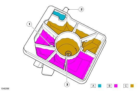
| Item Number | Description |
|---|---|
| 1 | Primary outlet |
| 2 | Clutch outlet |
| 3 | Secondary outlet |
The filler neck of the reservoir is sealed with a cap incorporating the level switch. The level switch is operated by a magnet, which is installed in the float on the bottom of the switch. The switch reacts to the influence of the magnetic field surrounding the magnet.
When the reservoir is full, the float rests against the bottom of the switch and holds the level switch open. When the fluid level decreases, the float moves down and the switch closes to connect a ground to the instrument cluster. When the ground is made, the instrument cluster illuminates the red Light Emitting Diode (LED) in the brake warning indicator. Vehicles with the high line instrument cluster also display an appropriate warning in the message center. Refer to Instrument Cluster information.
At the beginning of each ignition cycle, the instrument cluster performs a bulb check on the brake warning indicator; the indicator is illuminated amber for 1.5 seconds, then red for 1.5 seconds.
The instrument cluster broadcasts the status of the brake fluid level, on the high speed Controller Area Network (CAN) bus, to the Anti-lock Brake System (ABS) module. Refer to Anti-Lock Control - Traction Control information.