Auxiliary Climate Control: ACCM
| Item Number | Description |
|---|---|
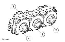
| 1 | Electrical connector |
| 2 | Blower switch |
| 3 | Distribution switch |
| 4 | Temperature switch |
The ACCM allows manual adjustment of the output from the auxiliary climate control assembly. The ACCM is installed in the headliner immediately behind the row 2 interior lamp. An integral control panel contains separate rotary switches for temperature, distribution and blower speed. When the ACCM is in manual mode, amber light emitting diode (LED)s in the switch surrounds illuminate to indicate the current settings of the system and function symbols in the switch surrounds are illuminated when the side lamps or headlamps are on.
The ACCM is disabled when the auxiliary climate control switch on the automatic temperature control (ATC) module is selected off. When the auxiliary climate control switch is selected to automatic or manual, the ACCM is enabled by the connection of a power feed from the automatic temperature control (ATC) module. The same power feed also supplies the stepper motors in the auxiliary climate control assembly.
When it is enabled, the ACCM operates as a slave unit to the automatic temperature control (ATC) module. The ACCM sends status signals on the LIN (local interconnect network) bus to the automatic temperature control (ATC) module, which replies with command signals of the required temperature, distribution and blower settings. The ACCM then outputs the necessary drive signals to the auxiliary climate control assembly:
- In the automatic mode, the command signals are derived from the comfort strategy in the automatic temperature control (ATC) module. The temperature setting is calculated from the mean of the two temperature settings on the automatic temperature control (ATC) module.
- In the manual mode, the command signals reflect the temperature, distribution and blower speed set by the switches on the ACCM control panel. Temperature control by the auxiliary climate control system may be compromised if the temperature settings on the automatic temperature control (ATC) module are set to maximum hot or cold.
ACCM Harness Connector C0695
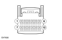
ACCM Harness Connector C0695 Pin Details
| Pin No. | Description | Input/Output |
|---|---|---|
| 1 | Power supply from automatic temperature control (ATC) module | Input |
| 2 | LIN bus | Input/Output |
| 3 | Ground | Output |
| 4 | Rear blower module power drive | Output |
| 5 | Blower motor voltage sense | Input |
| 6 | Cabin temperature sensor signal | Input |
| 7and 8 | Not used | - |
| 9 | Sensor ground | Output |
| 10 | Rear blower relay coil drive | Output |
| 11 | Solenoid valve drive | Output |
| 12 | Evaporator temperature sensor signal | Input |