Control Module
The control module controls and monitors operation of the FFBH system. An internal flow of air from the combustion air fan ventilates the control module to prevent it overheating.
The control module communicates with other systems on the vehicle over the medium speed Controller Area Network (CAN) bus.
FFBH Control Module Harness Connector C0925
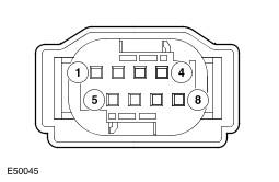
| Pin No. | Description | Input/Output |
|---|---|---|
| 1 | Not used | - |
| 2 and 3 | Not used | - |
| 4 | Medium speed controller area network (CAN) bus low | Input/Output |
| 5 | Auxiliary fuel pump power feed | Output |
| 6 | Not used | - |
| 7 | Medium speed CAN bus high | Input/Output |
| 8 | Not used | - |
FFBH Control Module Harness Connector C0926
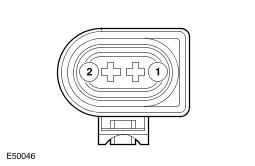
| Pin No. | Description | Input/Output |
| 1 | Permanent battery power supply | Input |
| 2 | Ground | Output |
Operation of the FFBH is controlled by a status message from the automatic temperature control (ATC) module to the control module. A similar status message, from the control module to the automatic temperature control (ATC) module, advises the automatic temperature control (ATC) module of the current operating status of the FFBH.
While the engine is running, if the ambient air temperature is less than 9 °C (48 °F) and the engine coolant temperature (ECT) is less than 75 °C (167 °F) the automatic temperature control (ATC) module changes the status message from 'heater off' to 'supplemental heat'. The control module then changes the status message it sends the automatic temperature control (ATC) module to 'supplemental heat' and starts the FFBH. The control module will not start the FFBH, or will discontinue operation, if any of the following occur:
- The control module is in the error lockout mode (see Diagnostics, below).
- A crash message is received from the restraints control module (RCM). For additional information, refer to: Air Bag and Safety Belt Pretensioner Supplemental Restraint System (SRS) (descop 501-20B).
- A low fuel level message is received from the instrument cluster. For additional information, refer to: Information and Message Center (descop 413-08).
- The engine is not running, or stops running for approximately 4 seconds. The time delay is included for stall protection.
If the control module does not start the FFBH, or discontinues operation, the status message to the automatic temperature control (ATC) module remains at, or changes to, 'heater off'. If the ambient air temperature increases to 9 °C (48 °F), or the engine coolant temperature (ECT) increases to 75 °C (167 °F), the automatic temperature control (ATC) module cancels supplementary heating, by changing the status message to the control module back to 'heater off'. The control module then cancels FFBH operation and changes the status message to the automatic temperature control (ATC) module to 'heater off'.
The FFBH is controlled at one of two heat output levels, 2.8 kW at part load combustion and 5 kW at full load combustion. The control module transmits the amount of fuel used by the FFBH to the instrument cluster, and the FFBH coolant temperature to the automatic temperature control (ATC) module.
Start Sequence: At the beginning of a start sequence, the control module energizes the glow pin function of the glow pin and flame sensor, to pre heat the combustion chamber, starts the combustion air fan at slow speed and energizes the coolant circulation pump. After approximately 30 seconds, the control module energizes the auxiliary fuel pump at the starting sequence speed. The fuel delivered by the auxiliary fuel pump evaporates in the combustion chamber, mixes with air from the combustion air fan and is ignited by the glow pin and flame sensor. The control module then progressively increases the speed of the auxiliary fuel pump and the combustion air fan. Once combustion is established the control module switches the glow pin and flame sensor from the glow pin function to the flame sensing function to monitor combustion. From the beginning of the start sequence to stable combustion at full load takes approximately 150 seconds.
Coolant Temperature Control: While the FFBH is running, the control module cycles the FFBH between full load combustion, part load combustion and a control idle phase of operation, depending on the temperature of the coolant in the heat exchanger.
Switching Point Diagram
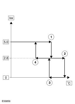
| Switching Point | Temperature, °C (°F) | |
|---|---|---|
| Figure Item No. | Description | |
| 1 | Full load to part load | 87 (188) |
| 2 | Part load to control idle | 90 (194) |
| 3 | Control idle to part load | 79 (174) |
| 4 | Part load to full load | 76 (168) |
After the start sequence, the control module maintains full load combustion until the coolant temperature reaches switching point temperature 1. At this temperature, the control module decreases the speed of the auxiliary fuel pump and the combustion air fan to half speed, to produce part load combustion. The control module maintains part load combustion while the coolant temperature remains between switching point temperatures 2 and 4. At part load combustion the temperature of the coolant will increase or decrease depending on the amount of heat required to heat the vehicle interior. If the coolant temperature decreases to switching point temperature 4, the control module increases the speed of the auxiliary fuel pump and the combustion air fan to full speed, to return to full load combustion. If the coolant temperature increases to switching point temperature 2, the control module enters a control idle phase of operation.
On entering the control idle phase, the control module immediately switches the auxiliary fuel pump off, to stop combustion, and starts a timer for the combustion air fan. After a 2 minute cool down period, the control module switches the combustion air fan off and then remains in the control idle phase while the coolant temperature remains above switching point temperature 3. If the coolant temperature decreases to switching point temperature 3, the control module initiates a start to part load combustion. A start to part load combustion takes approximately 90 seconds.
In order to limit the build up of carbon deposits on the glow pin and flame sensor, the control module also enters the control idle phase if continuous combustion time exceeds 72 minutes (at part load, full load or a combination of both). After the cool down period, if the coolant is still in the temperature range that requires additional heat, the control module restarts the FFBH.
Shutdown: To stop the FFBH, the control module de-energizes the auxiliary fuel pump to stop combustion, but continues operation of the combustion air fan and the circulation pump for a time, to cool down the FFBH. The cool down time is 100 seconds if the FFBH was operating at part load combustion and 175 seconds if the FFBH was operating at full load combustion.