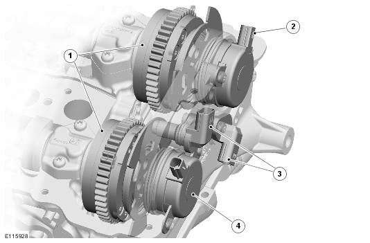
Variable Camshaft Timing
| Item Number | Description |
|---|---|
| 1 | VCT units |
| 2 | Intake camshaft VCT solenoid |
| 3 | Camshaft position sensors |
| 4 | Exhaust camshaft VCT solenoid |
The variable camshaft timing (VCT) system varies the timing of the intake and exhaust camshafts to deliver optimum engine power, efficiency and emissions. The timing of the intake camshafts has a range of 62 degrees of crankshaft angle. The timing of the exhaust camshafts has a range of 50 degrees of crankshaft angle.
In the base timing position:
- The intake camshafts are fully retarded.
- The exhaust camshafts are fully advanced.
variable camshaft timing (VCT) Operating Ranges
| Camshaft | Valve Opens | Valve Closes |
|---|---|---|
| Intake - Low Lift | 27 degrees before top dead center (BTDC) to 35 degrees after top dead center (ATDC) | 187 to 249 degrees after top dead center (ATDC) |
| Intake - High Lift | 37 degrees before top dead center (BTDC) to 25 degrees after top dead center (ATDC) | 213 to 275 degrees after top dead center (ATDC) |
| Exhaust | 244 to 194 degrees before top dead center (BTDC) | 6 to 56 degrees after top dead center (ATDC) |
The system consists of a variable camshaft timing (VCT) unit and a variable camshaft timing (VCT) solenoid for each camshaft. The engine control module (ECM) controls the system using pulse width modulation (PWM) signals to the variable camshaft timing (VCT) solenoids.
The torsional energy generated by the valve springs and the inertia of the valve train components are used to operate the system.
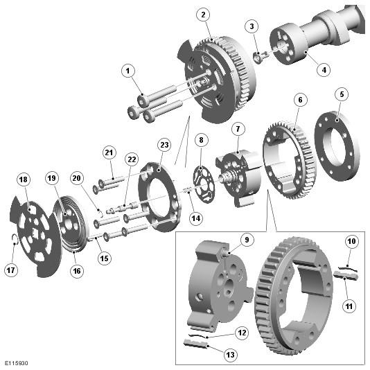
Variable Camshaft Timing Units
The variable camshaft timing (VCT) units change the position of the camshafts in relation to the timing chains.
| Item Number | Description |
|---|---|
| 1 | Bolt (3 off) |
| 2 | VCT unit |
| 3 | Filter |
| 4 | Camshaft |
| 5 | Inner plate |
| 6 | Housing and sprocket |
| 7 | Rotor assembly |
| 8 | Reed plate |
| 9 | Spring and lock pin |
| 10 | Spring (3 off) |
| 11 | Tip seal (3 off) |
| 12 | Spring (2 off) |
| 13 | Tip seal (2 off) |
| 14 | Spring |
| 15 | Dowel pin |
| 16 | Bias spring |
| 17 | Snap ring |
| 18 | Reluctor ring |
| 19 | Center plate |
| 20 | Snap ring |
| 21 | Screw (6 off) |
| 22 | Spool valve |
| 23 | Outer plate |
Each variable camshaft timing (VCT) unit is attached to the camshaft by three bolts. A rotor assembly and a reed plate are installed inside a sprocket housing, which consists of a sprocket, an outer plate and an inner plate held together by six screws.
A reluctor ring, for the camshaft position (CMP) sensor, a center plate and a bias spring are installed at the front of the variable camshaft timing (VCT) unit. The ends of the bias spring locate on the center plate assembly and the sprocket housing, to give a turning moment to the camshaft in the advance direction. A snap ring locates the reluctor ring on to a sleeve installed in the center of the rotor assembly. The opposite end of the sleeve locates in a bore in the front face of the camshaft, which contains a filter.
A spring and spool valve are installed in the rotor assembly sleeve and retained by a snap ring. The spring keeps the spool valve in contact with the armature of the related variable camshaft timing (VCT) solenoid.
Each variable camshaft timing (VCT) unit is supplied with engine oil from an oil gallery in the cylinder head, through the camshaft front bearing cap and a bore in the center of the camshaft.
Variable Camshaft Timing Solenoids
The variable camshaft timing (VCT) solenoids control the position of the spool valves in the variable camshaft timing (VCT) units.
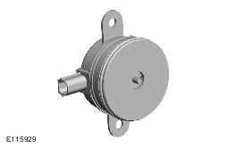
The variable camshaft timing (VCT) solenoids are installed in the front upper timing covers, immediately in front of their related variable camshaft timing (VCT) units. Each variable camshaft timing (VCT) solenoid is secured with two screws and sealed with an O-ring. A two pin electrical connector provides the interface with the engine harness.
Each variable camshaft timing (VCT) solenoid incorporates a spindle that acts on the spool valve in the related variable camshaft timing (VCT) unit to advance and retard the camshaft timing. The variable camshaft timing (VCT) solenoids operate independently and are controlled by a pulse width modulation (PWM) signal from the engine control module (ECM).
Variable Camshaft Timing Operation
When the engine is running, the compression and expansion of the valve springs causes momentary increases and decreases in the torque acting on the camshafts. These momentary changes of torque are sensed in the variable camshaft timing (VCT) units and used to change the camshaft timing.
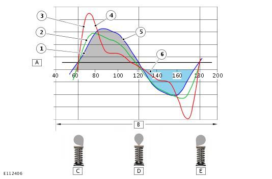
Camshaft Torsional Energy (For a Single Valve Event)
| Item Number | Description |
|---|---|
| A | Camshaft torque |
| B | Camshaft rotation (degrees) |
| C | Valve opening |
| D | Peak lift |
| E | Valve closing |
| 1 | 1000 rev/min |
| 2 | 4000 rev/min |
| 3 | 7000 rev/min |
| 4 | Inertia effects from valve train rotating components |
| 5 | Force caused by valve spring |
| 6 | Bias torque from friction |
Variable Camshaft Timing Unit Schematic - Base Timing
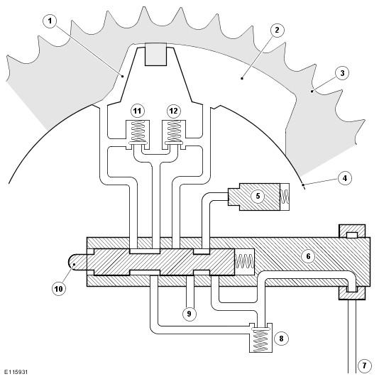
| Item Number | Description |
|---|---|
| 1 | Advance chamber |
| 2 | Retard chamber |
| 3 | Sprocket housing |
| 4 | Rotor assembly |
| 5 | Lock pin |
| 6 | Sleeve |
| 7 | Engine oil supply from camshaft |
| 8 | Inlet check valve |
| 9 | Lock pin drain |
| 10 | Spool valve |
| 11 | Advance check valve |
| 12 | Retard check valve |
At engine start-up, once the engine oil pressure in the camshaft is sufficient to open the inlet check valve, engine oil flows across the spool valve, through the advance and retard check valves and into the advance and retard chambers. During the start cycle, the engine control module (ECM) signals the variable camshaft timing (VCT) solenoid to move the spool valve into the sleeve and connect the lock pin to inlet oil pressure. The inlet oil pressure causes the lock pin to retract from the inner plate and unlock the rotor assembly and camshaft from the sprocket housing.
There is a constant supply of oil to the variable camshaft timing (VCT) to ensure the unit remains filled during operation.
Variable Camshaft Timing Unit Schematic - Advance
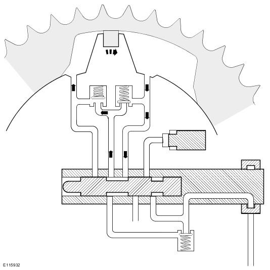
To advance the camshaft timing, the engine control module (ECM) adjusts the signal to the variable camshaft timing (VCT) solenoid to move the spool valve so that the advance chamber oil passage is closed and the retard chamber oil passage is connected to inlet oil.
Each momentary increase of the torque acting on the camshaft generates a pressure pulse in the retard chamber. Oil moves from the retard chamber, through the spool valve and the advance check valve to the advance chamber, to equalize the pressures in the two chambers. The displacement of oil from the retard chamber causes the rotor assembly to advance in relation to the sprocket housing. Each momentary decrease of torque acting on the camshaft also generates a pressure pulse in the advance chamber, but, with the advance chamber oil passage closed, no movement of oil between the advance and retard chambers occurs and the rotor assembly cannot move in the retard direction.
Variable Camshaft Timing Unit Schematic - Null
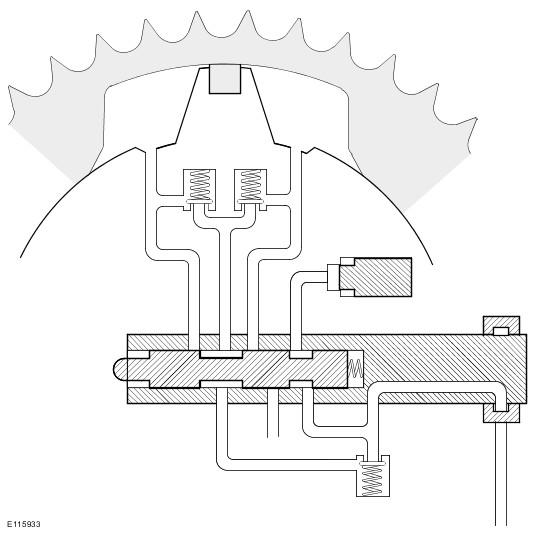
Once the camshaft has reached the required timing position the engine control module (ECM) adjusts the signal to the variable camshaft timing (VCT) solenoid to set the spool valve in the null position. In the null position, the advance and retard chamber oil passages are both closed by the spool valve and the rotor assembly is hydraulically locked to the sprocket housing.
Variable Camshaft Timing Unit Schematic - Retard
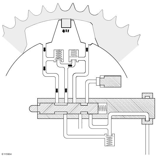
To retard the camshaft timing, the engine control module (ECM) adjusts the signal to the variable camshaft timing (VCT) solenoid to move the spool valve to close the retard chamber oil passage and connect the advance chamber oil passage to the inlet oil.
Each momentary decrease of the torque acting on the camshaft causes oil to transfer from the advance chamber, through the spool valve and the retard check valve to the retard chamber, and so retard the camshaft timing.