Timing Drive Components: Installation
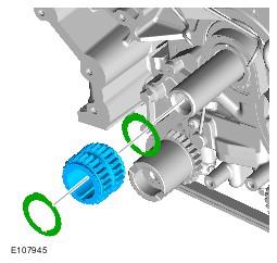
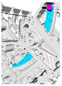
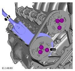
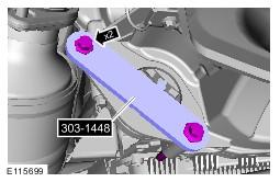
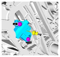
- See figure
- Torque: 12 Nm
-
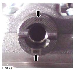
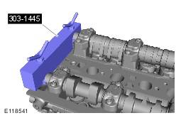
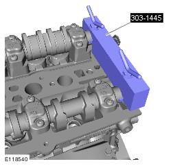
- Install the special tool 303-1445 to the rear of the camshafts making sure the key way's are correctly located into each slot on each of the camshafts.
-
- Using a suitable tool, carefully rock the camshaft clockwise then anti-clockwise. Turn the special tool locking nuts until there is no movement left in camshafts.
- Repeat steps 3- 6 for the camshafts on the other cylinder head.
-
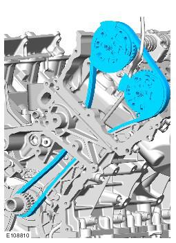
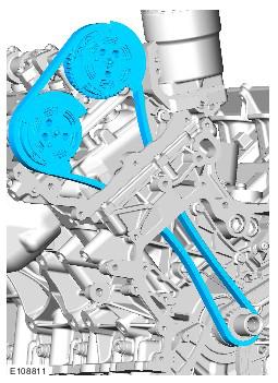
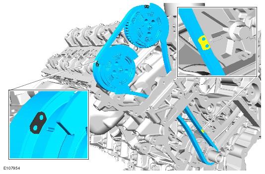
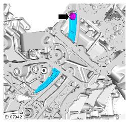
- Install the timing chain with the variable valve timing (VVT) units.
-
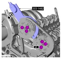
- Make sure that all the timing chain alignment marks are in the positions shown.
- Torque: 25 Nm
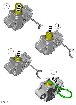
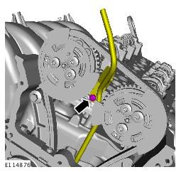
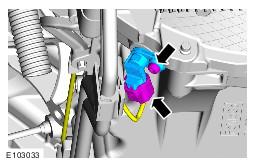
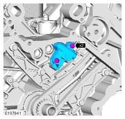
- Make sure the tensioner piston is fully extended. Then fully depress and lock the tensioner piston with the grenade pin before installation, failure to do this may result in damage to the engine.
- Torque: 10 Nm
-
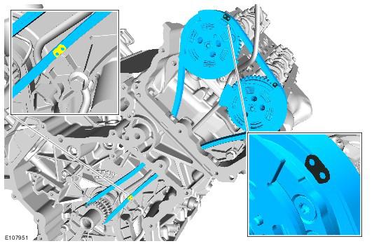
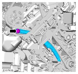
- Install the timing chain with the VVT units.
-
- Make sure that all the timing chain alignment marks are in the positions shown.
- Torque: 25 Nm
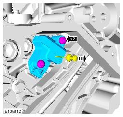
- Make sure the tensioner piston is fully extended. Then fully depress and lock the tensioner piston with the grenade pin before installation, failure to do this may result in damage to the engine.
- Torque: 10 Nm
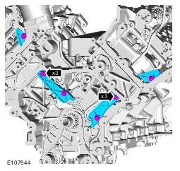
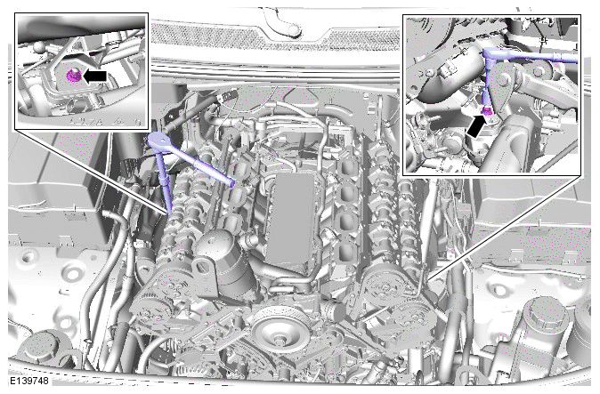
- See Figure
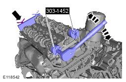
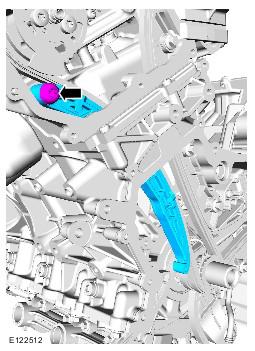
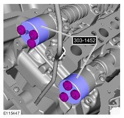
- Make sure that the tensioners are fully deployed.
- See Figure
- See Figure
-
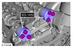
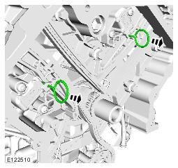
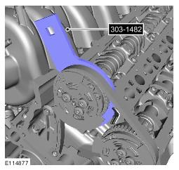
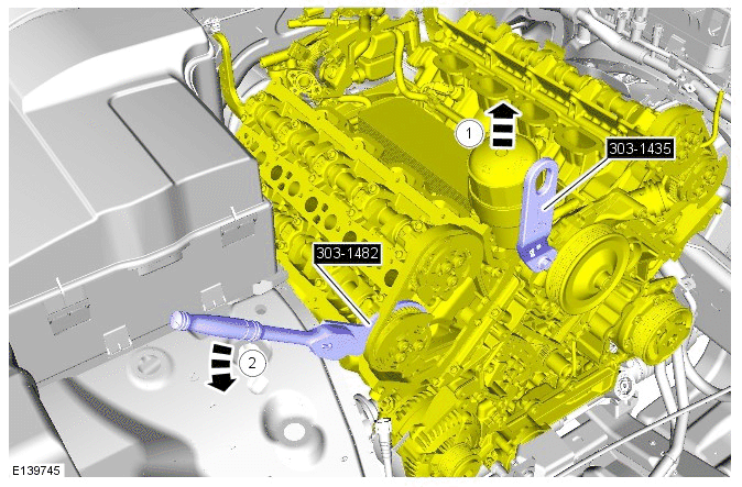
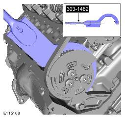
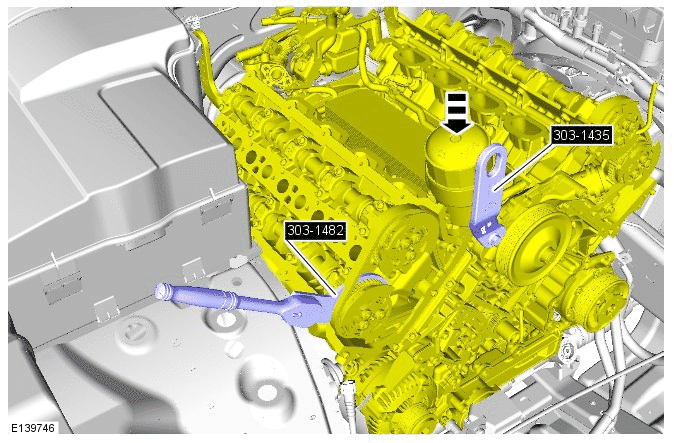
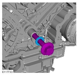
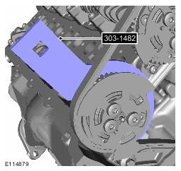
- Raise and support the engine, then install the special tool.
- Tensioner Tool: 303-1482
- Torque: 32 Nm
- Torque: 50 Nm
- Rotate the engine two complete turns clockwise.
- See Figure
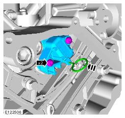
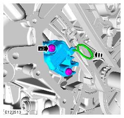
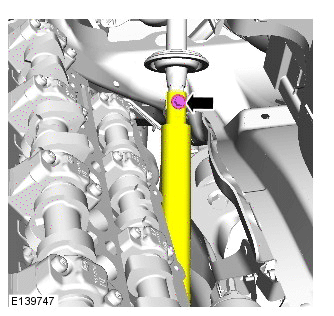
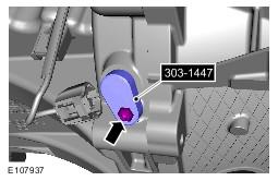
- Install the special tool.
Timing Tool - Camshaft Alignment (303-1445)
- Install the special tool.
- Torque: 10 Nm
- Refer to: TIMING COVER .
- Connect the battery ground cable. Refer to SPECIFICATIONS information.
CAUTION:
Install a new friction washer.
CAUTION:
Do not overturn the camshafts.
CAUTION:
Tighten the wing nuts finger tight. Failure to follow this instruction may result in damage to the components.
CAUTION:
Do not allow the camshaft to rotate.
CAUTION:
If the VVT is knocked or dropped then the VVT must be replaced.
NOTE:
Do not tighten at this stage.
CAUTION:
Do not release the timing chain tensioner locking pin at this stage.
CAUTION:
Do not allow the camshafts to rotate.
CAUTION:
If the VVT is knocked or dropped then the VVT must be replaced.
NOTE:
Do not tighten at this stage.
CAUTION:
Do not release the timing chain tensioner locking pin at this stage.
CAUTION:
Do not use mechanical force.
CAUTION:
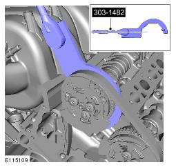
Apply the torque to the end of the special tool.
CAUTION:
Make sure that the torque wrench is aligned with the special tool as illustrated in the graphic.
CAUTION:
Make sure that the torque wrench does not move whilst tightening the VVT bolts.
NOTE:
Make sure to tighten the exhaust VVT unit bolts first.
CAUTION:
Apply the torque to the end of the special tool.
CAUTION:
Make sure that the torque wrench is aligned with the special tool as illustrated in the graphic.
CAUTION:
Make sure that the torque wrench does not move whilst tightening the VVT bolts.
NOTE:
Make sure to tighten the inlet VVT unit bolts first.
CAUTION:
Install the crankshaft pulley bolt with an M16 washer to prevent damage to the crankshaft on installation.
CAUTION:
Only rotate the crankshaft clockwise.
CAUTION:
If the special tool cannot be installed, return to step 22 of the installation until the special tool 303-1445 is installed correctly.
CAUTION:
If directed to step 22, make sure that the VVT unit retaining bolts are loosened prior to installing the special tool(s).
CAUTION:
If the special tool cannot be installed, the timing chain installation steps must be repeated.
- See figure
- Torque: 12 Nm
- Torque: 25 Nm
- Torque: 10 Nm
- Torque: 25 Nm
- Make sure that the tensioners are fully deployed.
Torque: 10 Nm
- Make sure that the tensioners are fully deployed.
Torque: 10 Nm
- Torque: 32 Nm
- Torque: 50 Nm
- Rotate the engine two complete turns clockwise.
- See Figure
- Install the special tool.
- Install the special tool.
- Torque: 10 Nm
- Refer to: TIMING COVER .
- Connect the battery ground cable. Refer to SPECIFICATION information.
CAUTION:
Install new friction washers.
CAUTION:
Do not overturn the camshafts.
CAUTION:
Tighten the wing nuts finger tight. Failure to follow this instruction may result in damage to the components.
CAUTION:
Do not allow the camshaft to rotate.
CAUTION:
If the VVT is knocked or dropped then the VVT must be replaced.
NOTE:
Do not tighten at this stage.
CAUTION:
Do not release the timing chain tensioner locking pin at this stage.
CAUTION:
Do not allow the camshafts to rotate.
CAUTION:
If the VVT is knocked or dropped then the VVT must be replaced.
NOTE:
Do not tighten at this stage.
CAUTION:
Do not use mechanical force.
CAUTION:
Do not use mechanical force.
CAUTION:
Apply the torque to the end of the special tool.
CAUTION:
Make sure that the torque wench is aligned with the special tool as illustrated in the graphic.
CAUTION:
Make sure that the torque wrench does not move whilst tightening the VVT bolts.
NOTE:
Make sure to tighten the exhaust VVT unit bolts first.
CAUTION:
Apply the torque to the end of the special tool.
CAUTION:
Make sure that the torque wench is aligned with the special tool as illustrated in the graphic.
CAUTION:
Make sure that the torque wrench does not move whilst tightening the VVT bolts.
NOTE:
Make sure to tighten the inlet VVT unit bolts first.
CAUTION:
Install the crankshaft pulley bolt with an M16 washer to prevent damage to the crankshaft on installation.
CAUTION:
Only rotate the crankshaft clockwise.
CAUTION:
If the special tool cannot be installed, return to step 22 of the installation until the special tool 303-1445 is installed correctly.
CAUTION:
If directed to step 22, make sure that the VVT unit retaining bolts are loosened prior to installing the special tool(s).
CAUTION:
If the special tool cannot be installed, the timing chain installation steps must be repeated.