Fuel Rail RH: Removal
Special Tool(s)
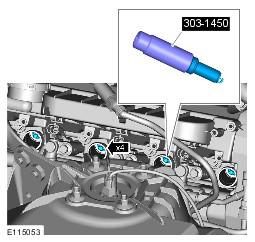
| Spark Plug Remover/Installer | |
| Remover, Fuel Injector | |
| Installer, Teflon Seal | |
| Re-shape Tool, Teflon Seal | |
| Fuel Rail Installation Guide Pins - Threaded | |
| Fuel Rail Installation Guide Pins - Unthreaded |
CAUTION:
Make sure that tools and equipment are clean and free of foreign material and lubricant.
CAUTION:
Always carry out the cleaning process before carrying out any repairs to the fuel injection system components. Failure to follow this instruction may result in foreign matter ingress to the fuel injection system.
NOTE:
Removal steps in this procedure may contain installation details.
NOTE:
Some variation in the illustrations may occur, but the essential information is always correct.
All vehicles
- Refer to Petrol and Petrol-Ethanol Fuel Systems Health and Safety Precautions information.
- Refer to Fuel System Pressure Release - V8 5.0L Petrol information.
- Disconnect the battery ground cable. Refer to Specifications information.
- Refer to Engine Cover - V8 5.0L Petrol information.
- Refer to Air Cleaner Outlet Pipe T-Connector information.
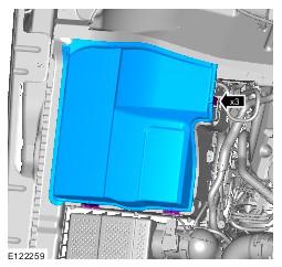
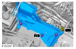
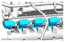
- See figure
- See figure
- See figure
- Refer to Battery information.
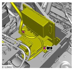
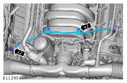
- See figure
- See figure
- See figure
- See figure
- Refer to Fuel Injection Component Cleaning .
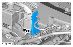
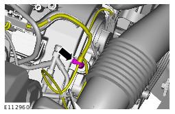
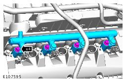
- See figure
- See figure
- See figure
- Raise and support the vehicle.
- Refer to Steering Gear - V8 5.0L Petrol information.
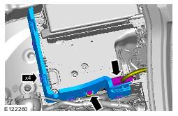
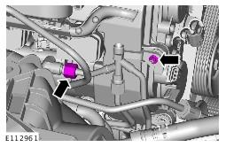
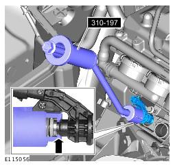
- See figure
- See figure
- Lower the vehicle.
- See figure
- See figure
- See figure
- See figure
- See figure
- See figure
- See figure
- See figure
- See figure
CAUTION:
Be prepared to collect escaping fluids.
CAUTION:
Be prepared to collect escaping fluids.
Left-hand drive vehicles
Right-hand drive vehicles
All vehicles
CAUTION:
Be prepared to collect escaping fluids.
CAUTION:
Make sure that all openings are sealed. Use new blanking caps.
CAUTION:
Be prepared to collect escaping fluids.
CAUTION:
Make sure that all openings are sealed. Use new blanking caps.
WARNING:
Do not work on or under a vehicle supported only by a jack. Always support the vehicle on safety stands.
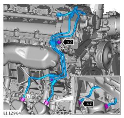
NOTE:
Engine shown removed for clarity.
CAUTION:
Be prepared to collect escaping fluids.
CAUTION:
Make sure that all openings are sealed. Use new blanking caps.
NOTE:
Engine shown removed for clarity.
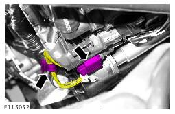
NOTE:
LH illustration shown, RH is similar.
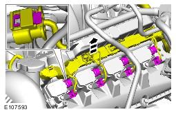
NOTE:
LH illustration shown, RH is similar.
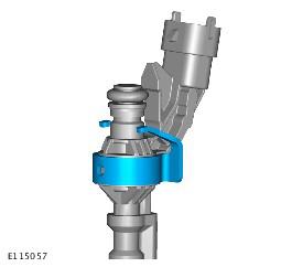
CAUTION:
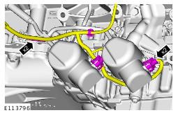
Make a note of the fuel injector clamp alignment to the fuel rail prior to removal.
NOTE:
LH illustration shown, RH is similar.
CAUTION:
Make sure that the special tool is located correctly to the fuel injector prior to removing the fuel injector.
CAUTION:
Make sure that the special tool is held square to the fuel injector during removal.
CAUTION:
Make sure that all open ports are covered to prevent any foreign material ingress.
CAUTION:
If the fuel injector is being removed without a new component being installed, the fuel injector clamp must remain with the fuel injector it is removed with.
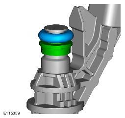
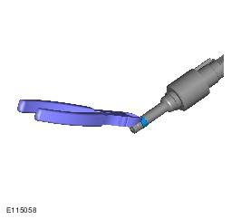
CAUTION:
Do not use a knife to remove the Teflon seal as damage could occur to the fuel injector.
CAUTION:
Do not cut the Teflon seal to deep as damage could occur to the fuel injector.
CAUTION:
Pinch the Teflon seal to allow the tool to cut the Teflon seal without damaging the fuel injector.
CAUTION:
Do not use any sharp tools to remove the O-ring seal as damage could occur to the fuel injector.