Body - (Petrol): Removal
NOTE:
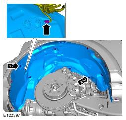
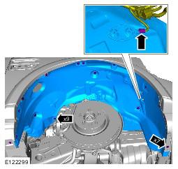
Some variation in the illustrations may occur, but the essential information is always correct.
NOTE:
Some illustrations may show the engine removed for clarity.
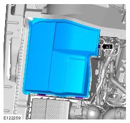
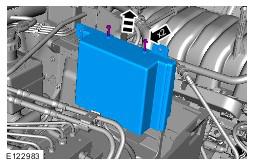
- Remove the battery cover. Refer to Battery information.
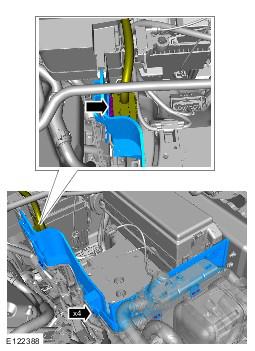
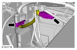
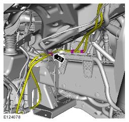
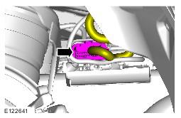
- See figure.
- See figure.
- See figure.
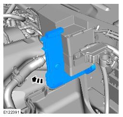
- See figure.
- See figure.
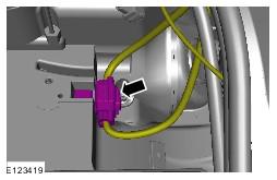
- See figure.
- See figure.
- Refer to Air Cleaner LH information.
- Refer to Air Cleaner RH information.
- Refer to Air Conditioning (A/C) System Recovery, Evacuation and Charging information.
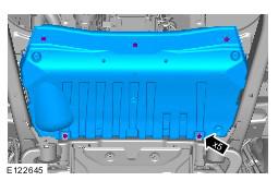
- Refer to Rear Bumper Cover information.
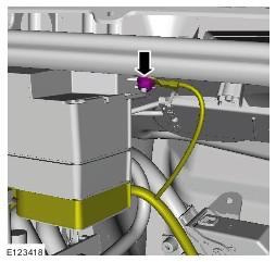
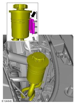
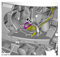
- See figure.
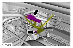
-
- Discard the O-ring seal.
-
- Discard the O-ring seal.
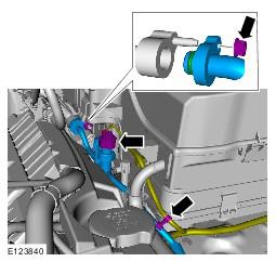
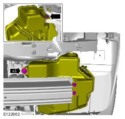
- See figure.
- See figure.
- See figure.
- Refer to Auxiliary Battery Tray
information.
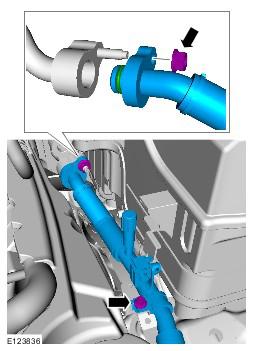
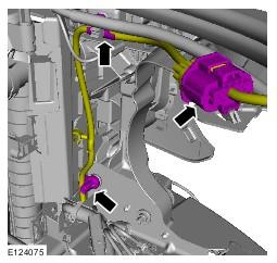
- See figure.
- See figure.
- See figure.
- Refer to Coolant Expansion Tank information.
- See figure.
- See figure.
- See figure.
- See figure.
- See figure.
- See figure.
- See figure.
- See figure.
- See figure.
- See figure.
- See figure.
- See figure.
- See figure.
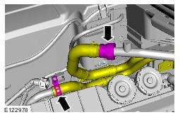
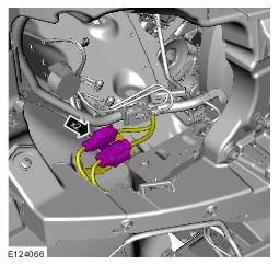
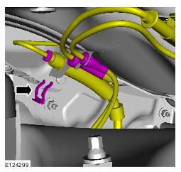
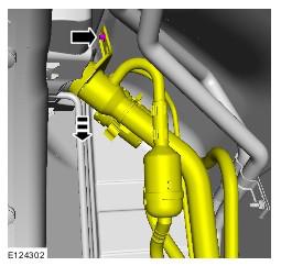
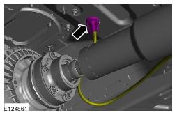
-
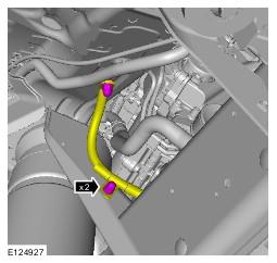
- Position an absorbent cloth to collect fluid spillage.
- Disconnect the line union.
- Remove the clip.
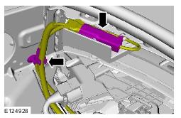
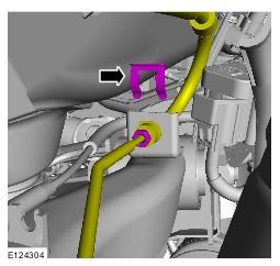
-
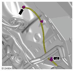
- Position an absorbent cloth to collect fluid spillage.
- Disconnect the line union.
- Remove the clip.
- See figure.
- Refer to Fuel Filler Door Assembly
information.
- Remove the fuel filler cap.
- See figure.
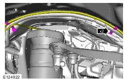
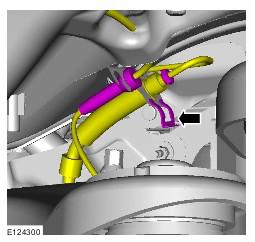
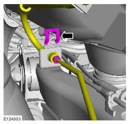
-
- Position an absorbent cloth to collect fluid spillage.
- Disconnect the line union.
- Remove the clip.
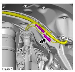
-
- Position an absorbent cloth to collect fluid spillage.
- Disconnect the line union.
- Remove the clip.
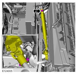
- See figure.
- See figure.
- See figure.
- See figure.
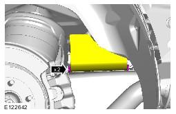
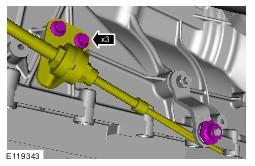
-
- Remove and discard the bolt.
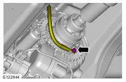
- See figure.
- Lower the vehicle.
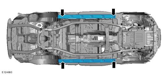
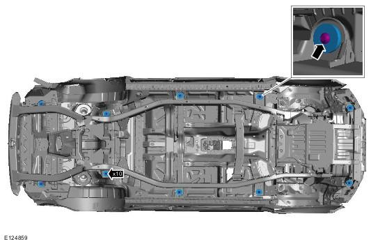
- See figure.
- Remove and discard the 10 body mount bolts.
- Remove the 10 spacing washers.
- Using an assistant raise and support the body.
- Remove the body mounts.
- See figure.
All vehicles
NOTE:
RHD illustration shown, LHD is similar.
Vehicles with active damping
All vehicles
CAUTION:
Make sure that all openings are sealed. Use new blanking caps.
CAUTION:
Make sure that all openings are sealed. Use new blanking caps.
WARNING:
Be prepared to collect escaping fluid.
CAUTION:
Before disconnecting or removing the components, make sure the area around the joint faces and connections are clean. Plug open connections to prevent contamination.
CAUTION:
Before disconnecting or removing the components, make sure the area around the joint faces and connections are clean. Plug open connections to prevent contamination.
CAUTION:
Before disconnecting or removing the components, make sure the area around the joint faces and connections are clean. Plug open connections to prevent contamination.
CAUTION:
Before disconnecting or removing the components, make sure the area around the joint faces and connections are clean. Plug open connections to prevent contamination.
CAUTION:
Note the fitted position of the seal.
CAUTION:
To prevent the body becoming unstable when raised from the integrated body frame, install the vehicle tie down straps.
NOTE:
Note the fitted position of the body mounts.