Frame Wiring Harness (Vehicles Built From: 01/2007): Removal
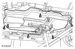
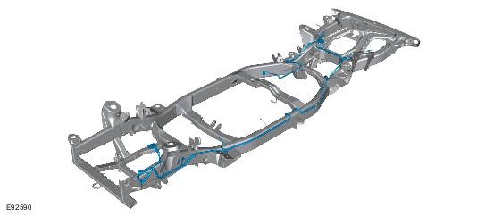
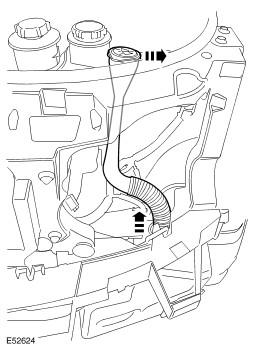
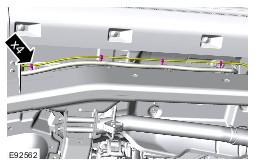
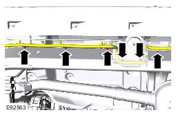
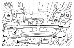
- The frame wiring harness routing.
- Open the upper liftgate and lower tailgate.
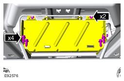
- Remove the spare wheel and tire.
- Raise and support the vehicle.
- Remove the wheels and tires.
- Disconnect the battery ground cable. Refer to: Specifications information.
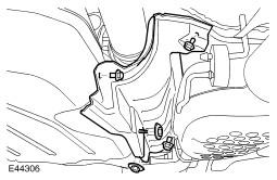
- Remove the LH front wheel arch liner. Refer to: Fender Splash Shield information.
- Remove the windshield washer reservoir filler neck.
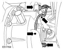
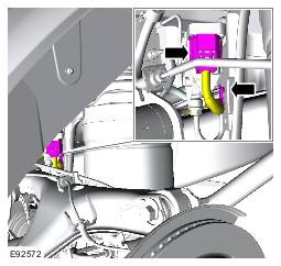
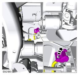
- LH side behind the front headlamp: Disconnect the frame wiring harness electrical connector.
- LH side behind the front panel: Disconnect the 2 electrical connectors from the frame wiring harness.
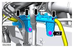
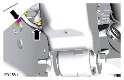
- LH side behind headlamp: Release the 2 clips from the inner fender.
- LH side behind headlamp: Reposition the frame wiring harness down to the inner fender.
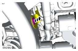
- LH side front: Release the 2 windshield washer jet hoses.
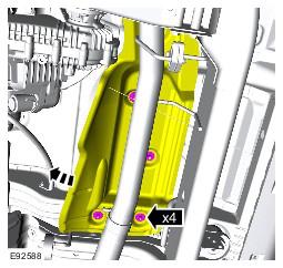
- Remove the frame wiring harness carrier.
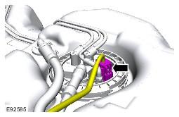
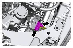
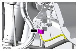
- LH side front: Disconnect the height sensor electrical connector.
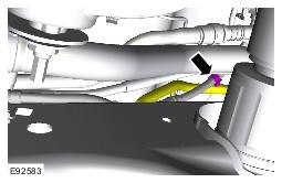
- Disconnect the ground cable from the wheel arch earth stud.
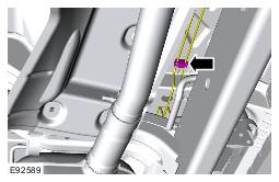
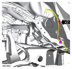
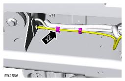
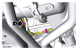
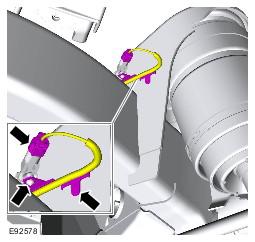
- LH front side: Release the frame wiring harness from the frame.
- Remove the air suspension reservoir. Refer to: Air Suspension Reservoir information.
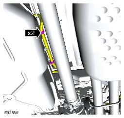
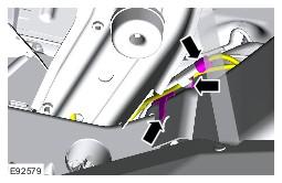
- LH side: Release air suspension line from the frame wiring harness.
- LH side: Release the frame wiring harness from the frame.
- Remove the air suspension silencer. Refer to: Air Suspension Muffler information.
- Remove the evaporative emission canister. information.
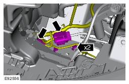
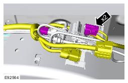
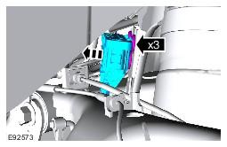
- Disconnect the 2 electrical connectors from the air suspension solenoid.
- Release the air suspension compressor valve block.
- LH side: Release air suspension line from the frame wiring harness.
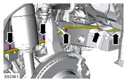
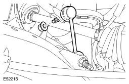
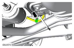
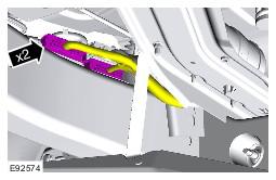
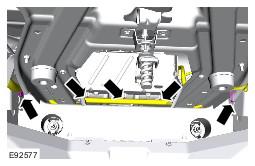
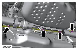
- Release both stabilizer bar links.
- Release the stabilizer bar.
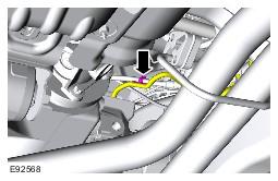
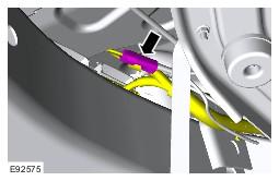
- Release the frame wiring harness from the parking brake cable.
- Vehicles with differential locking motor: Disconnect the 2 electrical connectors.
- Release the parking brake emergency release cable.
- LH side: Release the frame wiring harness.
- Disconnect the electrical connector from the rear LH height sensor.
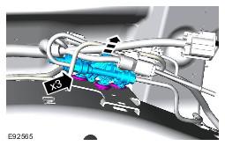
- LH side rear: Disconnect the air suspension rear valve block electrical connector.
- Release the valve block from its mounting bracket.
- Reposition the frame wiring harness to above the frame.
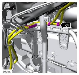
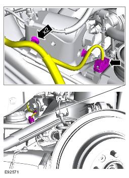
- LH side rear: Disconnect the 2 electrical connectors from the frame wiring harness.
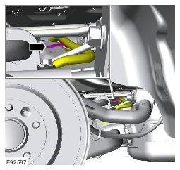
- Disconnect the LH rear ABS sensor.
- Release the parking brake actuator mount bracket.
- Spare wheel aperture: Release the frame wiring harness.
- RH side rear: Disconnect the ABS sensor electrical connector.
- RH side rear: Disconnect the low brake pad warning lamp electrical connector.
- Disconnect the electronic parking brake actuator electrical connector.
- Release the RH parking brake cable.
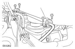
- Release the fuel line support bracket.
- Release the frame wiring harness from the parking brake cable.
- RH side: Release the frame wiring harness from the frame.
- Remove the transmission under shield.
- Remove the fuel tank heat shield.
- Release the parking brake emergency release cable.
- Using a transmission jack, lower the fuel tank.
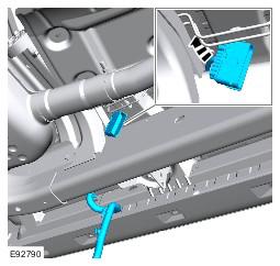
- Disconnect the fuel pump module electrical connector.
- Release the frame wiring harness from the fuel tank.
- Rear of fuel tank: Release the frame wiring harness from the top of the frame crossmember.
- Secure the fuel tank.
- Release the exhaust heat shield for access.
- Release the brake pipes.
- With assistance, remove the frame wiring harness.
All vehicles
NOTE:
All of the clips on the harness can be access with the integrated body installed to the frame. The graphic is to give guidance of the routing of the harness.
WARNING:
Do not work on or under a vehicle supported only by a jack. Always support the vehicle on safety stands.
All except vehicles with diesel engine
All vehicles
CAUTION:
Use a wrench on the hexagon provided to prevent the ball joint rotating.
WARNING:
Secure the component to the transmission jack.
CAUTION:
Note the rear bolt is fitted with 2 washers.