Front Parking Aid Camera Wiring Harness - Front Section (RHD AWD): Installation
- Install the camera overlay wiring harness
- Remove the connector from the camera overlay wiring harness.
- Using suitable tape, secure a suitable rod to the camera overlay wiring harness.
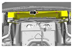
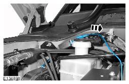
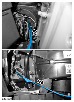
- Carefully feed the camera overlay wiring harness under the bracket.
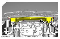
- Carefully feed the camera overlay wiring harness through the wiring harness carrier.
- Carefully feed the camera overlay wiring harness through the wiring harness carrier.
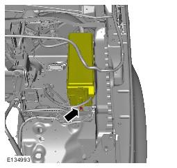
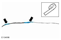
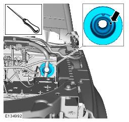
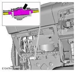
- Using a suitable tool, make a hole in grommet in the position shown.
- With the aid of another technician, carefully feed the camera overlay wiring harness through the grommet.
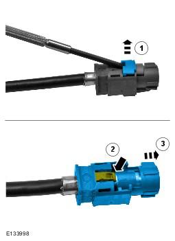
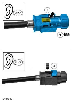
- Install the connector to the camera overlay wiring harness.
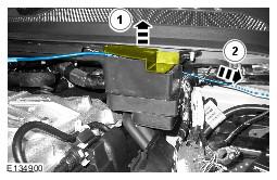
- Connect the electrical connector.
- Connect the electrical connector.
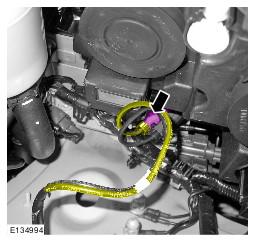
- Using suitable tie straps, secure the camera overlay wiring harness to the main body wiring harness.
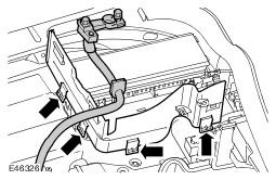
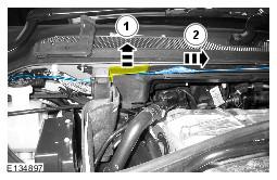
- Secure the 3 clips.
- Secure the wiring harness carrier.
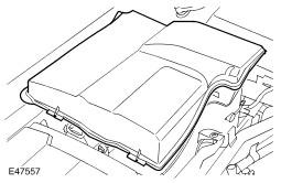
- Secure the engine compartment fuse box.
- Install the battery compartment side wall.
- Install the air cleaner.
- Install the brake master cylinder cover.
- Secure the hood seal.
- Install the CJB. Refer to: Central Junction Box (CJB) information.
- Install the battery. Refer to: Battery information.
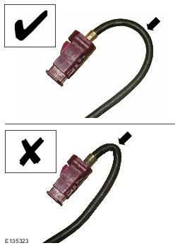
CAUTION:
Make sure that the camera overlay wiring harness is not bent excessively during this procedure. Failure to follow this instruction may result in damage to the harness.
NOTE:
Some variation in the illustrations may occur, but the essential information is always correct.
NOTE:
Some variation in the illustrations may occur, but the essential information is always correct.
NOTE:
The left hand front camera wiring harness connectors are coloured magenta, the right hand front camera wiring harness connectors are coloured blue.
NOTE:
The left hand front camera wiring harness connectors are coloured white, the right hand front camera wiring harness connectors are coloured green.
CAUTION:
Make sure that excessive force is not used when installing the tie straps to the wiring harness. Failure to follow this instruction may result in damage to the harness.