Parking Aid Camera Signal Filter: Installation
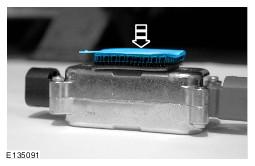
- Secure one piece of the dual lock tape to the parking aid camera signal filter.
- Remove the backing strip from the dual lock tape.
- Secure another piece of the dual lock tape to the parking aid camera signal filter.
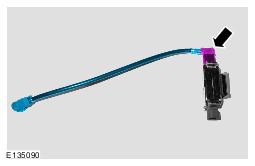
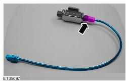
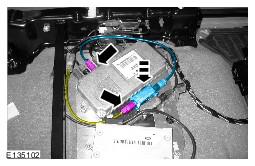
- Install the link lead to the parking aid camera signal filter.
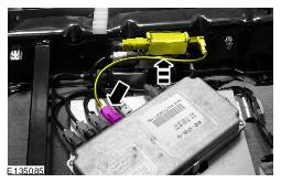
- Connect the parking aid camera signal filter assembly to the camera wiring harness.
- Connect the camera wiring harness link lead to the module.
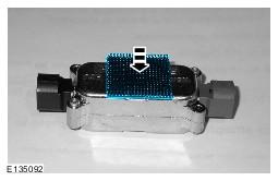
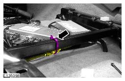
- Secure the parking aid camera signal filter to the seat base in the position shown.
- Remove the backing strip from the dual lock tape.
- Secure the parking aid camera signal filter to the seat base in the position shown.
- Remove the backing strip from the dual lock tape.
- Secure the parking aid camera signal filter to the seat base in the position shown.
- Remove the backing strip from the dual lock tape.
- Install the longer link lead to the parking aid camera signal filter.
- Install the shorter link lead to the camera wiring harness.
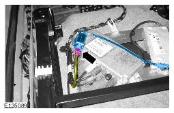
- Install the parking aid camera signal filter assembly.
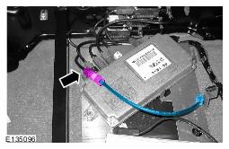
- Connect the parking aid camera signal filter assembly to the module.
- Connect the parking aid camera signal filter assembly to the camera wiring harness link lead.
- Remove the backing strip from the dual lock tape.
- Secure the parking aid camera signal filter to the vehicle in the position shown.
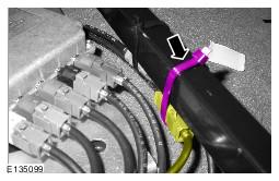
- Using a suitable tie strap, secure the camera wiring harness to the seat base in the position shown.
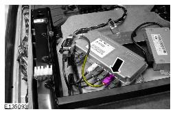
- Install the parking aid camera signal filter assembly.
- Connect the parking aid camera signal filter assembly to the module.
- Connect the parking aid camera signal filter assembly to the camera wiring harness link lead.
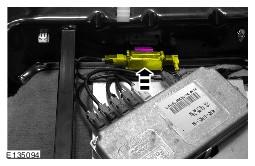
- Remove the backing strip from the dual lock tape.
- Secure the parking aid camera signal filter to the vehicle in the position shown.
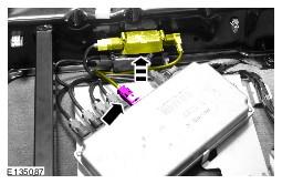
- Using a suitable tie strap, secure the camera wiring harness to the seat base in the position shown.
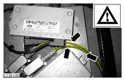
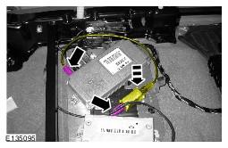
- Make sure that the wiring harness is correctly routed and does not contact against the modules in the positions shown.
NOTE:
Make sure that the dual lock tape is adhered to the side of the parking aid camera signal filter that has writing on.
CAUTION:
Do not remove the backing strip from the second piece of dual lock tape.
NOTE:
RH front camera, LH front camera and rear camera only.
NOTE:
RH front camera, LH front camera and rear camera only.
NOTE:
RH front camera shown, LH front camera and rear camera similar.
NOTE:
RH front camera, LH front camera and rear camera only.
NOTE:
RH front camera shown, LH front camera and rear camera similar.
NOTE:
RH front camera only
NOTE:
Make sure that the parking aid camera signal filter is in the correct position before securing the dual lock tape to the seat base.
NOTE:
LH front camera only
NOTE:
Make sure that the parking aid camera signal filter is in the correct position before securing the dual lock tape to the seat base.
NOTE:
Rear camera only
NOTE:
Make sure that the parking aid camera signal filter is in the correct position before securing the dual lock tape to the seat base.
NOTE:
RH side view camera and LH side view camera only
NOTE:
RH side view camera and LH side view camera only
NOTE:
RH side view camera shown, LH side view camera similar.
NOTE:
RH side view camera only.
NOTE:
Make sure that the parking aid camera signal filter is in the correct position before securing the dual lock tape to the vehicle.
NOTE:
RH side view camera only.
NOTE:
LH side view camera only.
NOTE:
Make sure that the parking aid camera signal filter is in the correct position before securing the dual lock tape to the vehicle.
NOTE:
LH side view camera only.
NOTE:
RH side view camera and LH side view camera only