Fuel Gauge Operation Inaccurate (LTB00566V6)
WARNING: This page is about the LR4 Base, which is a different variant/trim than selected.
Publication date: 2014-10-10Reference number: LTB00566V6
Supersedes refnos: LTB00566NAS1, LTB00566NAS2, LTB00566NAS4
FUEL GAUGE OPERATION INACCURATE
TECHNICAL SERVICE BULLETIN
Reference Number(s): LTB00566NAS4, Date of Issue:
October 10, 2014
| LAND ROVER: | 2010-2013 LR4 (LA); 2008-2012 LR2 (LF); 2010-2013 Range Rover Sport (LS); 2010-2012 Range Rover (LM) |
| SECTION: | 310-01 |
| AFFECTED VEHICLES: | LR4 (LA) VIN: AA510742-DA656034 Model Year: 2010-2013; LR2 (LF) VIN: 8H000212-CH292666 Model Year: 2008-2012; Range Rover Sport (LS) VIN: AA212147-DA790997 Model Year: 2010-2013; Range Rover (LM) VIN: AA304426-CA369495 Model Year: 2010-2012 |
NOTE:
This reissue replaces all previous versions. Please destroy all previous versions. Only refer to the electronic version of this Technical Bulletin in TOPIx.
MARKETS
NAS
CONDITION SUMMARY
Situation: The fuel gauge may be inoperative or inaccurate.
Cause: These issues may be caused by fretting corrosion across the fuel sender harness pins inside the fuel tank.
NOTE:
Advise the customer to bring the vehicle in with the fuel tank level below 1/4 full.
Action: Should a customer express this concern, follow the Service Instruction outlined below.
PARTS
CAUTION:
The splice joint connector is specific to this repair and must be used and crimped using special tool 418-116A/YRW500010.
PARTS DESCRIPTION
| LR050538 | Splice joint connector | Quantity: 6 |
| LR000966 | Gasket - LR2, LR4, Range Rover Sport | Quantity: 1 |
| ESR3806 | Gasket - Range Rover | Quantity: 2 |
TOOLS
Crimping pliers
WARRANTY
NOTE:
Repair procedures are under constant review, and therefore times are subject to change; those quoted here must be taken as guidance only. Always refer to TOPIx to obtain the latest repair time.
NOTE:
DDW requires the use of causal part numbers. Labor only claims must show the causal part number with a quantity of zero.
| DESCRIPTION | SRO | TIME (HOURS) | CONDITION CODE | CAUSAL PART |
|---|---|---|---|---|
| Fuel sender harness modification - LR2 (L359) | 88.25.89/35 | 2.6 | X2 | LR038723 |
| Fuel sender harness modification - LR4 (L319) | 88.25.89/35 | 1.5 | X2 | LR042971 |
| Fuel sender harness modification - Range Rover Sport (L320) | 88.25.89/35 | 1.5 | X2 | LR042716 |
| Fuel sender harness modification - Range Rover (L322) | 88.25.89/35 | 1.5 | X2 | LR043153 |
NOTE:
Normal Warranty policies and procedures apply.
SERVICE INSTRUCTION
- Remove the fuel pump and sender unit/fuel pump module (see TOPIx Workshop Manual, Section 310-01).
- Place the fuel pump and sender unit/fuel pump module on a clean work surface.CAUTION: To reduce the chance of incorrect wiring of the harnesses, wherever possible, only repair one wire at a time.CAUTION: Make sure that the splice is crimped in the correct location.CAUTION: Make sure that the splice is crimped using special tool 418-116A/YRW500010.CAUTION: Make sure that the splice with the part number listed above is used. Failure to follow these instructions may result in a poor repair.NOTE: The number of black connectors shown in the fuel tank on a vehicle may vary from the procedure shown below. To achieve the best possible repair, replace as many of the black connectors (up to three [3 in total) as possible.NOTE: Some variation in the illustrations may occur, but the essential information is always correct.
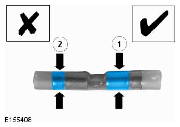
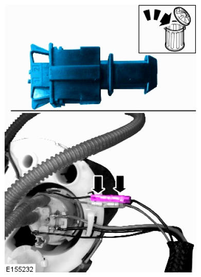
- When installing the splices, make sure that the splice is crimped in the correct location.
- 'Tick'/'1' - correct crimp location.
- 'X'/'2' - incorrect crimp location.
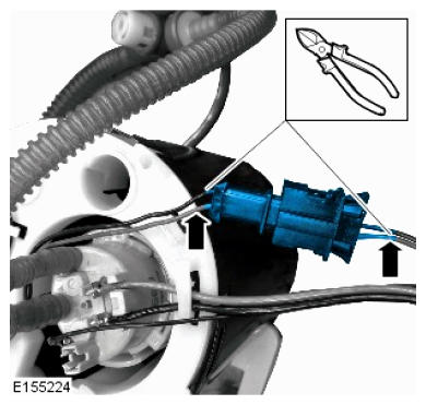
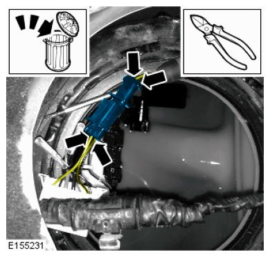
CAUTION: Make sure the wiring is cut as close to the connector as possible.NOTE: A total of three (3) black two-pin connectors may be found. Replace only one at a time. - Identify a black two-pin connector to be removed.
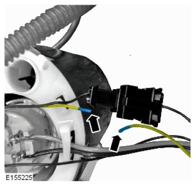
- Using a suitable tool, remove 5mm of insulation from the end of each wire.CAUTION: After crimping the connection, perform a gentle pull test to make sure that a sufficiently strong connection has been created. If required, remove and replace the splice.
- Using Crimping Tool 418-116A/YRW500010, install and crimp a splice to the ends of each wire.
- Repeat steps 5-6 to the other wire in the connector.
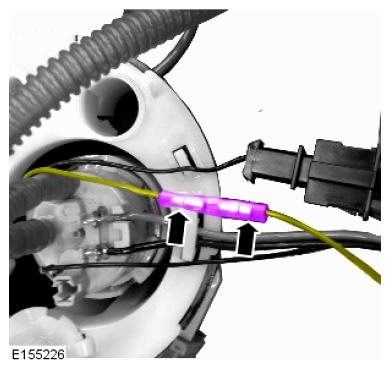
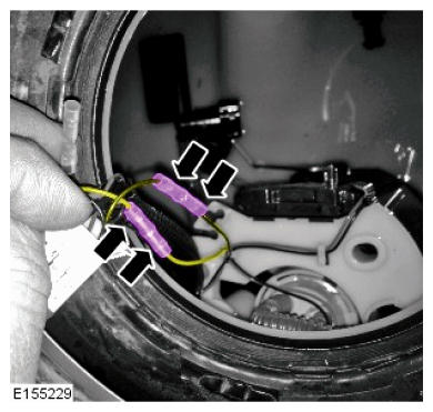
- Repeat steps 4-7 to all black two-pin connectors (up to three [3] in total).
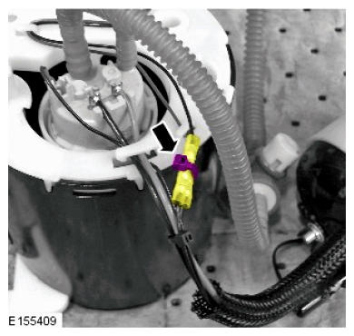
- Using a suitable tie strap, secure the two splices together.CAUTION: Make sure the wiring is cut as close to the connector as possible.
- Identify the ground connector (two black wires) to be removed.
- Using a suitable tool, remove 5mm of insulation from the end of each wire.NOTE: Do not connect the two splices until step 16.
- Using Crimping Tool 418-116A/YRW500010, install and crimp a splice to the end of each wire.CAUTION: Do not install the fuel tank flange at this point.
- Install the fuel pump and sender unit/fuel pump module into the fuel tank (see TOPIx Workshop Manual, Section 310-01).CAUTION: Make sure the wiring is cut as close to the connector as possible.CAUTION: Make sure that the correct wires are re-connected to each other.
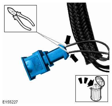
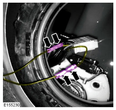
- Identify the connector to be removed.
- Carefully withdraw the connector out of the tank.
- Cut the wires shown as close to the connector as possible.
- Discard the connector.
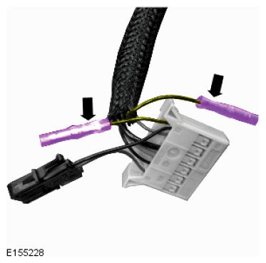
CAUTION: After crimping the connection, perform a gentle pull test to make sure that a sufficiently strong connection has been created. If required, remove and replace the splice. - Using a suitable tool, remove 5mm of insulation from the end of each wire.
- Using Crimping Tool 418-116A/YRW500010, install and crimp a splice to the ends of each wire.
- Using a suitable tie strap, secure the two splices together.
CAUTION: After crimping the connection, perform a gentle pull test to make sure that a sufficiently strong connection has been created. If required, remove and replace the splice. - Connect the two ground wires from the base of the fuel tank flange to the two splices installed in step 12.
- Measure the resistance values of the fuel gauge sending units.
- Compare the resistance values obtained to the Resistance Values Checks chart below.
- If the resistance values are correct, continue to the next step.
- If the resistance values are not correct, further diagnosis is required. Must be performed as a separate claim.
CAUTION: A successful resistance values check (step 17) must be carried out before continuing to install the fuel pump and sender unit/fuel pump module. - Compare the resistance values obtained to the Resistance Values Checks chart below.
- Complete the installation of the fuel pump and sender unit/fuel pump module (see TOPIx Workshop Manual, Section 310-01).
- Read and clear all Diagnostic Trouble Codes (DTC).
Resistance Values Checks
| Check No. | Pin No. | Lower Resistance Value (Ohms) | Upper Resistance Value (Ohms) | |
|---|---|---|---|---|
| 1 | 1 | 2 | 46.2 | 1002.2 |
| 2 | 1 | 6 | 46.2 | 1002.2 |