Handbook Doesn't Correctly Detail Spare Wheel Procedure After Winch Replacement (SSM71618)
Reference number: SSM71618
HANDBOOK DOESN'T CORRECTLY DETAIL SPARE WHEEL PROCEDURE AFTER WINCH REPLACEMENT
TECHNICAL SERVICE BULLETIN
| LAND ROVER: | Range Rover Sport/L320, LR3/L319, LR4/L319 |
| CATEGORY: | Chassis |
SERVICE INFORMATION
Symptom 307000 Jack/Tool & Spare
ISSUE
The vehicle handbook doesn't correctly detail the spare wheel removal procedure after the vehicle has had a new winch fitted.
CAUSE
Land Rover changed the method for using the winch to lower the spare wheel from the vehicle. Older vehicles will have a nut that is then turned by the wheel brace. Vehicles built after the following cut offs:
L319 - 659872
L320 - 795860
Content
have the later style winch with a hole that the vehicle jack hook is then inserted in before being rotated.
If a vehicle pre the above VINs has a winch replacement, they will get the later style winch. The tool kit will still be fully functional but the owners hand book will be incorrect.
ACTION
If an old style winch is replaced with a new style then please print the relevant pages attached to this SSM and give them to the vehicle owner. Please also explain the new method of operation when returning the vehicle to the customer.
WHEEL CHANGING
7 seat vehicles: The tool kit is stowed behind an access cover in the loadspace area.
REMOVING THE SPARE WHEEL
The spare wheel is heavy and if handled incorrectly may cause injury. Use extreme caution when lifting or maneuvering the wheels.
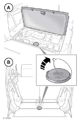
On 5 seat vehicles (A):
- Open the rear loadspace floor panel.
- Remove the cover for access to the spare wheel hoist winch spindle.
- Remove all of the tools from the vehicle's tool kit. See 218, TOOL KIT.
On 7 seat vehicles (B):
- Behind the 3rd row seats, remove the cover for access to the spare wheel hoist winch spindle.
- Remove all of the tools from the vehicle's tool kit. See 218, TOOL KIT.
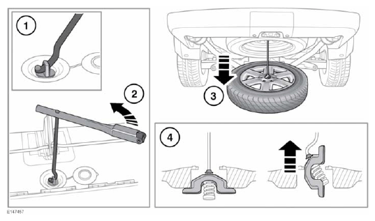
- Fit the jack handle through the hole in the winch spindle.
- Fit the wheel brace onto the jack handle and rotate counter-clockwise to lower the spare wheel.
- Continue to turn the wheel hoist winch, until the wheel is on the ground and the hoist cable is slack.NOTE: Do not attempt to turn the winch past its physical stop.
- Hold the cable and tilt the lifting lug until it can be passed through the hole in the wheel.
USING WHEEL CHOCKS
REMOVING THE SPARE WHEEL
The spare wheel is heavy and if handled incorrectly may cause injury. Use extreme caution when lifting or maneuvering the wheels.
Secure the spare wheel (or the removed wheel) in the correct position using the retaining bolt.
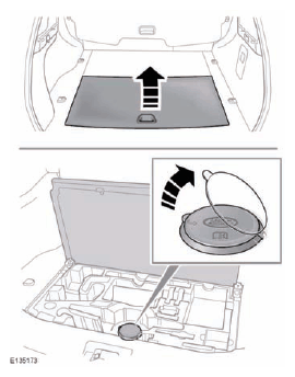
- Open the spare wheel access hatch in the loadspace area and remove the vehicle jack from the tool tray.
- Lift the cap covering the spare wheel hoist winch spindle.
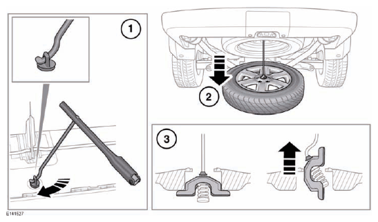
- Fit the jack handle through the hole in the winch spindle. Fit the wheel brace onto the jack handle and rotate anticlockwise to lower the spare wheel.
- Continue to turn the wheel hoist winch nut, until the wheel is on the ground and the hoist cable is slack. Do not attempt to turn the winch nut past its physical stop.
- Hold the cable and tilt the lifting lug until it can be passed through the hole in the wheel, as shown.