Wheel/Tire Balancing And Optimization (LTB00401NAS6)
Reference number: LTB00401NAS6
Supersedes refnos: LTB00401NAS2
WHEEL/TIRE BALANCING AND OPTIMIZATION
TECHNICAL SERVICE BULLETIN
| LAND ROVER: | 2017 Onwards Discovery (LR); 2012 Onwards Range Rover Evoque (LV); 2016 Onwards Range Rover Evoque (LV); 2018 Onwards Range Rover Velar (LY); 2014 Onwards Range Rover Sport (LW); 2013 Onwards Range Rover (LG); 2002-2005 Freelander (LN); 2007-2015 LR2 (LF); 2005-2009 LR3 (LA); 2010-2016 LR4 (LA); 2006-2013 Range Rover Sport (LS); 2003-2012 Range Rover (LM) |
| SECTION: | 204-04: Wheels and Tires |
| AFFECTED VEHICLE RANGE: | Discovery (LR) MODEL YEAR: 2017 Onwards VIN: 000532 Onwards ASSEMBLY PLANT: Solihull; Range Rover Evoque (LV) MODEL YEAR: 2012 Onwards VIN: 000447 Onwards ASSEMBLY PLANT: Halewood APPLICABILITY: 3-Door/5-Door; Range Rover Evoque (LV) MODEL YEAR: 2016 Onwards VIN: 091969 Onwards ASSEMBLY PLANT: Halewood APPLICABILITY: Folding Top; Range Rover Velar (LY) MODEL YEAR: 2018 Onwards VIN: 700125 Onwards ASSEMBLY PLANT: Solihull; Range Rover Sport (LW) MODEL YEAR: 2014 Onwards VIN: 000002 Onwards ASSEMBLY PLANT: Solihull; Range Rover (LG) MODEL YEAR: 2013 Onwards VIN: 001204 Onwards ASSEMBLY PLANT: Solihull; Freelander (LN) MODEL YEAR: 2002-2005 VIN: 353298-419396 ASSEMBLY PLANT: Halewood; LR2 (LF) MODEL YEAR: 2007-2015 VIN: 000212-439912 ASSEMBLY PLANT: Halewood; LR3 (LA) MODEL YEAR: 2005-2009 VIN: 000360-513325 ASSEMBLY PLANT: Solihull; LR4 (LA) MODEL YEAR: 2010-2016 VIN: 510742-847658 ASSEMBLY PLANT: Solihull; Range Rover Sport (LS) MODEL YEAR: 2006-2013 VIN: 900129-814822 ASSEMBLY PLANT: Solihull; Range Rover (LM) MODEL YEAR: 2003-2012 VIN: 101029-393639 ASSEMBLY PLANT: Solihull |
MARKETS
NORTH AMERICA
CONDITION SUMMARY
SITUATION:
The steering wheel may exhibit a vibration / shimmy while driving.
CAUSE:
This may be caused by a road wheel/tire assembly imbalance and/or temporary tire flat spotting.
ACTION:
Should a customer express this concern, follow the information below.
PARTS
| DESCRIPTION | QUANTITY |
|---|---|
| Wheel weights - Locally sourced | As required |
TOOLS
| Jaguar Land Rover-approved Midtronics battery power supply | |
| Jaguar Land Rover-approved diagnostic tool with latest SDD Software Management Pack | |
| Inline Diagnostic equipment (IDU) 2 | |
| Noise, Vibration and Harshness (NVH) Sensor Steering wheel mount |
WARRANTY
- Repair procedures are under constant review, and therefore times are subject to change; those quoted here must be taken as guidance only. Always refer to JLR claims submission system to obtain the latest repair time.
- The JLR Claims Submission System requires the use of causal part numbers. Labor only claims must show the causal part number with a quantity of zero.
| DESCRIPTION | SRO | TIME (HOURS) | CONDITION CODE | CAUSAL PART |
|---|---|---|---|---|
| 10 mile road test - Wheel shimmy/vibration test | 74.10.89.40 | 0.30 | 42 | LR037742 |
| 20 mile road test - Wheel shimmy/vibration test | 74.10.89.60 | 0.70 | 42 | LR037742 |
| Road wheel balance - vehicle set - and road test | 74.10.89.39 | 2.2 I | 42 | LR037742 |
SERVICE INSTRUCTION 'A'
-
NOTE: Factory wheel alignment and wheel balancing are covered for 12 months/12,500 mi (20,000 Km), whichever occurs first, for OEM equipment only. Refer to Warranty Compliance and Procedures Manual for further information.
No claim should be submitted with reference to this Technical Bulletin where wheel shimmy was identified and rectified during the normal length Pre-Delivery Inspection (PDI) road test.
Until flat spots are removed, significant wheel vibration/shimmy/vehicle vibration may be present, even if the car has only stood overnight. A test drive is required to ensure temporary tire flat spots are removed. For longer term flat spots, a longer drive may be required. The test drive should be carried out on normal open roads to allow the highest speed that speed limits and road / traffic conditions allow.
All road tests must be performed with tire pressures at 29psi / 2.0bar / 200kPa.If the vehicle has experienced a steering wheel vibration / shimmy during the Pre-Delivery Inspection (PDI) road test, refer to Technical Bulletin LTB00466NAS. If after performing the Service Instruction therein the concern is still evident, go to the Diagnostic Procedure below.
SERVICE INFORMATION
| MODEL | MODEL YEAR (MY) |
|---|---|
| Discovery Sport (L550) | 2015-17MY |
| Range Rover Evoque - Folding top (L538c) | 2016MY |
| Range Rover Evoque - (L538) | 2016-17MY |
| Range Rover Sport (L494) | 2014-16MY |
| Range Rover (L405) | 201316MY |
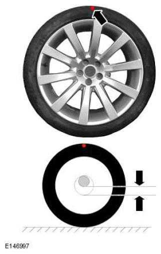
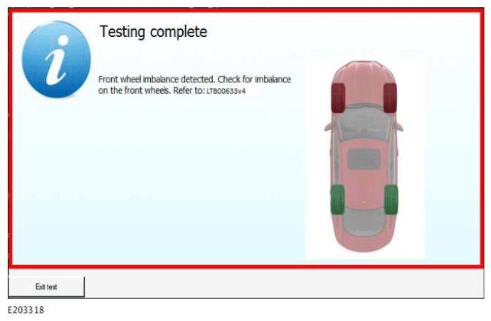
The illustration shows an example of front wheel and tire assembly imbalance. On completion of the diagnostic procedure below, the test results will identify if there is front, rear, front and rear, or no wheel imbalance detected.
-
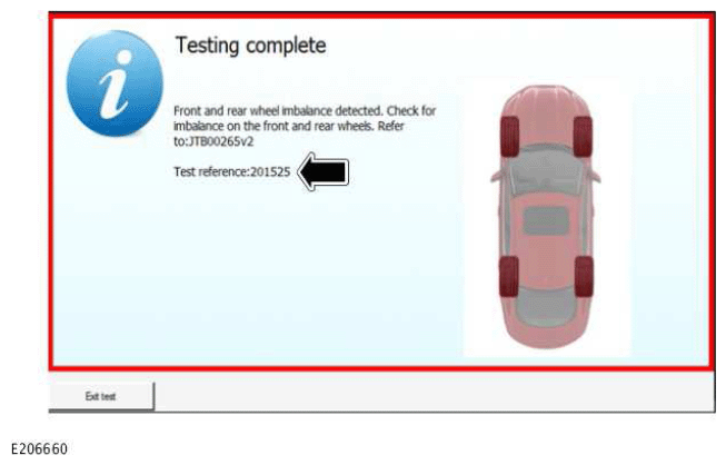
NOTE: This information must be added to the retailer verbatim of the claim, otherwise the claim will be rejected.
Record the test reference number produced at the end of the diagnostic test in the warranty claim submission.
DIAGNOSTIC PROCEDURE: SDD
This Diagnostic Procedure is only for vehicles requiring the Jaguar Land Rover-approved diagnostic tool with Symptom Driven Diagnostics (SDD).
- A Jaguar Land Rover-approved Midtronics battery power supply must be connected to the vehicle startup battery during diagnosis / module programming.
- All ignition ON/OFF requests must be carried out. Failure to perform these steps may cause damage to control modules in the vehicle.
-
Connect the Jaguar Land Rover-approved Midtronics battery power supply to the vehicle startup battery.
-
NOTE: The Jaguar Land Rover-approved diagnostic tool must be loaded with SDD152.05 Software Management Pack v290 (or later).
Connect the Jaguar Land Rover-approved diagnostic tool to the vehicle and begin a new session. - Follow all on-screen instructions, allowing the diagnostic tool to read the VIN, identify the vehicle, and initiating the data collect sequence.
- If the hyperlink is not available:
- Select Diagnosis from the Session Type screen.
- Select the Selected Symptoms tab.
- Select Chassis - Steering system - Steering system symptoms
- Select continue .
- Select the Recommendations tab.
- Select Run to perform the 'Special applications - Inline diagnostic unit 2 noise vibration and harshness diagnostic test - Wheel imbalance' option.
- Disconnect the battery power supply.
- If a road test was completed during the Diagnostic Procedure, go to Step 7.
- If a road test was not completed during the diagnostic procedure, go to Step 8.
- Assess the level of wheel vibration/shimmy.
- If the amount of wheel vibration/shimmy is acceptable after the Diagnostic Procedure road test, go to Step 11; do not continue with this Technical Bulletin.
- Return the vehicle to the customer with a full explanation of the situation/flat spot scenario and how it can/does affect the drive of the vehicle until the wheels and tires reach normal operating temperature.
- If the amount of wheel vibration/shimmy is unacceptable, go to Step 9.
- If the amount of wheel vibration/shimmy is acceptable after the Diagnostic Procedure road test, go to Step 11; do not continue with this Technical Bulletin.
- NOTE: Only complete this step if a road test was not completed during the diagnostic procedure.
Road test the vehicle a minimum of 16 Km (10 mi).
- Assess the level of wheel vibration/shimmy.
- If the amount of wheel vibration/shimmy is acceptable after the Diagnostic Procedure road test, go to Step 11; do not continue with this Technical Bulletin.
- Return the vehicle to the customer with a full explanation of the situation/flat spot scenario and how it can/does affect the drive of the vehicle until the wheels and tires reach normal operating temperature.
- If the amount of wheel vibration/shimmy is unacceptable, go to Step 9.
- If the amount of wheel vibration/shimmy is acceptable after the Diagnostic Procedure road test, go to Step 11; do not continue with this Technical Bulletin.
- Assess the level of wheel vibration/shimmy.
- Road test the vehicle a minimum of 16 Km (10 mi) to confirm if the wheel vibration/shimmy is caused by flat spotted tires or incorrectly balanced wheel and tire assemblies.
-
If the wheel vibration/shimmy is caused by flat spotted tires or incorrectly balanced wheel and tire assemblies, perform to Steps 11- 12 then go to Step 3 of 'Service Instruction B'.
- Exit the current session.
- Select the Session tab.
- Select the Close Session option.
- Disconnect the diagnostic tool from the vehicle.
SERVICE INSTRUCTION 'B'
- Road test the vehicle a minimum of 16 Km (10 mi). 1 Assess the level of wheel vibration/shimmy.
- If the amount of wheel vibration/shimmy is acceptable after the Diagnostic Procedure road test, do not continue with this Technical Bulletin.
- Return the vehicle to the customer with a full explanation of the situation/flat spot scenario and how it can/does affect the drive of the vehicle until the wheels and tires reach normal operating temperature.
- If the amount of wheel vibration/shimmy is unacceptable, go to Step 2.
- If the amount of wheel vibration/shimmy is acceptable after the Diagnostic Procedure road test, do not continue with this Technical Bulletin.
- Road test the vehicle a minimum of 16 Km (10 mi) to confirm if the wheel vibration/shimmy is caused by flat spotted tires or incorrectly balanced wheel and tire assemblies.
- If the wheel vibration/shimmy is caused by flat spotted tires or incorrectly balanced wheel and tire assemblies, go to Step 3.
- Adjust tire pressures to the recommended (cold) settings.
- Road test the vehicle for approximately 8 Km (5 mi) at speeds up to approximately 80 Km/h (50 mph [if possible]).
- If the amount of wheel vibration/shimmy is acceptable, do not continue with this Technical Bulletin.
- Return the vehicle to the customer with a full explanation of the situation/flat spot scenario and how it can/does affect the drive of the vehicle until the wheels and tires reach normal operating temperature.
- If the amount of wheel vibration/shimmy is unacceptable, raise and support the vehicle immediately upon returning to the workshop (see TOPIx Workshop Manual section 100-02: Jacking and Lifting).
- If the amount of wheel vibration/shimmy is acceptable, do not continue with this Technical Bulletin.
- Remove all four road wheel and tire assemblies (see TOPIx Workshop Manual section 204-04: Wheels and Tires).
- Adjust the tire pressures to 36psi / 2.5bar / 250kPa.
- Balance each wheel and tire assembly until the residual imbalance dynamic is minimized.
- Target is 0g (zero grams) on each plane; maximum is inner 5g / outer 5g.
- Use the 'bulls-eye' balancing mode to minimize residual imbalance.
- Balance each wheel and tire assembly until the residual imbalance dynamic is minimized.
- The maximum Radial Force Variation (RFV) values should be as follows:
- 60N (6.1kg, 13.5lbf) First Harmonic
- 100N (10.2kg, 22.5lbf) Peak to Peak
-
NOTE: If the RFV equipment is not available and the tire has not been removed from the wheel and the RFV spot (red dot) is still visible, this should be installed at the top.
If these levels cannot be achieved, perform the following:
- Remove the tire.
- Follow the match mounting procedure as detailed by the wheel balance machine.
- Mark the high point of the 1st harmonic RFV on the outer (and inner for future reference) sidewall of the tire.
- On vehicles installed with electric power steering: Install the lowest 1st harmonic RFV wheel/tire assemblies to the rear axle. On vehicles installed with hydraulic power steering: Install the lowest 1st harmonic RFV wheel/tire assemblies to the front axle.
- Print out the results of the balance and force variation (before and after), and attach to the repair order.
Prior to tightening the wheel nuts, the high-point of RFV should be marked and the road wheel and tire assembly installed to the vehicle with the RFV high point at the top.
-
NOTE: Nothing should be used to brace the wheel while tightening the nuts as this can disturb the match mounting.
Install all four wheel and tire assemblies (see TOPIx Workshop Manual section 204-04: Wheels and Tires).
- Adjust tire pressures to recommended (cold) settings.
- Drive the vehicle for 7 Km (5 mi) on normal roads up to speeds of approximately 80 km/h (50 mph) to verify the wheel vibration/shimmy has been rectified.
- Return the vehicle to the customer with a full explanation of the situation/flat spot scenario, and how it can/does affect driving the vehicle until the wheel and tire reaches normal operating temperature.