Land Rover Tire Pressure Monitoring System (TPMS) Diagnostic (LTB00542V2)
Reference number: LTB00542V2
Supersedes refnos: LTB00542NAS1
LAND ROVER TIRE PRESSURE MONITORING SYSTEM (TPMS) DIAGNOSTIC
TECHNICAL SERVICE BULLETIN
| LAND ROVER: | 2010 Onwards Discovery 4 / LR4 (LA); 2007 Onwards Freelander 2/LR2 (LF); 2013 Onwards Range Rover (LG); 2010-2012 Range Rover (LM); 2010-2013 Range Rover Sport (LS); 2012 Onwards Range Rover Evoque (LV) |
| SECTION: | 419-00 |
| AFFECTED VEHICLES: | Discovery 4 / LR4 (LA) Model Year: 2010 Onwards VIN: 510178 Onwards Manufacturing Plant: Solihull; Freelander 2/LR2 (LF) Model Year: 2007 Onwards VIN: 000201 Onwards Manufacturing Plant: Halewood; Range Rover (LG) Model Year: 2013 Onwards VIN: 000001 Onwards Manufacturing Plant: Solihull; Range Rover (LM) Model Year: 2010-2012 VIN: 302697-393639 Manufacturing Plant: Solihull; Range Rover Sport (LS) Model Year: 2010-2013 VIN: 212145-814822 Manufacturing Plant: Solihull; Range Rover Evoque (LV) Model Year: 2012 Onwards VIN: 000200 Onwards Manufacturing Plant: Halewood |
This bulletin supersedes TSB LTB00542/2013 dated 02 MAY 2013, which should either be destroyed or clearly marked to show it is no longer valid (e.g. with a line across the page). Only refer to the electronic version of this Technical Bulletin in TOPIx.
CONDITION SUMMARY
Situation:
A customer may express a concern that a Tire Pressure Monitoring System (TPMS) fault may be displayed in the Instrument Cluster (IC).
A technician will find TPMS related faults stored in the Tire Pressure Monitoring System Control Module (TPMSCM).
This version has been issued to update the Affected Vehicle Range and the Service Information sections.
Cause: This may be caused by various issues.
Action: Should a customer express this concern, refer to the SERVICE INFORMATION below.
PARTS
No Parts Required
TOOLS
JLR approved diagnostic tool (SDD)
SDD DVD142.04 and Calibration File 213 loaded or later
JLR approved battery support unit

SERVICE INFORMATION
- New symptom and DTC mapping is available on SDD DVD142.04 and calibration file 213 loaded or later. In addition there are new service diagnostic functions which must be used when recommended by SDD or TOPIx. The new diagnostic functions include -
- Integrated Tire Pressure Monitoring System diagnostics for 14MY vehicles and above.
- Tire Pressure Monitoring System wheel sensor test for all applications with the Integrated Tire Pressure Monitoring system.
- The new service diagnostic functions will improve the time taken and accuracy in the diagnosis of TPMS issues. It is advised to interrogate one of the following symptoms in SDD:
- Electrical - Instruments - Warning lamps - TPMS lamp illuminated:
- TPMS Warning Lamp permanently ON for 20 seconds at ignition ON and then goes OFF.
- TPMS Warning Lamp permanently ON at ignition ON.
- TPMS Warning Lamp flashes for 75 seconds at ignition ON and then stays permanently ON.
Service Parts
- Electrical - Instruments - Warning lamps - TPMS lamp illuminated:
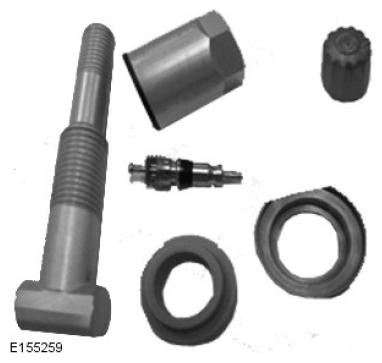
- New service kits have been released for dealers. These are in vehicle kits with an economic advantage to encourage improved servicing of the sensor at a tire change. It is recognised that lack of servicing is leading to the reduced life of the valve. The correct kit should always be used. Photos in Step 10 and 12 help differentiate between the 2 mechanical styles and illustrate the service kits available for each design.
Inaccurate use of Bulletin LTB00376
- It is vital this bulletin is accurately followed and in particular the diagnostic check to make sure the specified DTC is set in isolation to any others.
Use of wrong part number parts
- When fitting new valve sensors, make sure the correct part number is used. Even similar looking valves can be different and application of the wrong part will lead to further problems with the system.
Damaged valves at a tire change
- Wheel units can become damaged during routine tire changes. When inspected the damage to the sensor housing is clearly visible. Equally, over tightening of the mounting nut during installation can result in housing failure. Clear instructions are available in TOPIx to make sure removal and installation can be completed without damage to the unit. In addition there is a helpful instruction sheet in the service kit which is required at a tire change.
Wrong level of a service part
- If a leak occurs between the valve stem and the wheel, the repair should be made using the correct valve service kit (see Steps 10 - 14 for helpful illustrations).
Incorrect valve core replacement
- Only the cores supplied with the valve and those in the valve service kits should be used in a TPMS valve. These can be identified by their silver color.
Excessive side loading of valve
- Care should be taken when handling the valve stem. Excessive side loading can damage the valve, as described in the Owner's Handbook. In the instance of the TG1C style valve, the stem can be replaced without replacing the complete sensor unit.
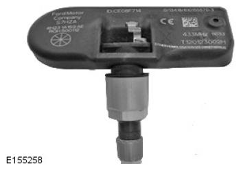
- TG1B Valve
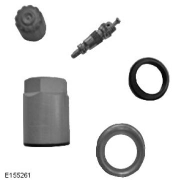
- TG1B Service kit.
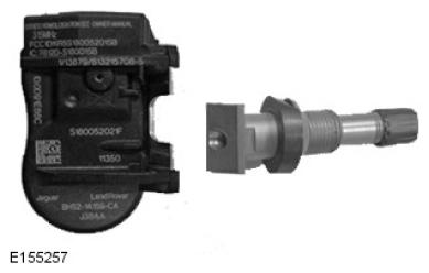
- TG1C Valve
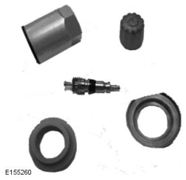
- TG1C service kit without stem.
- TG1C service kit with stem.