Four-Wheel Alignment
Special Tools
| Tool Illustration | Tool Name | Tool Number |
|---|---|---|
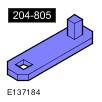
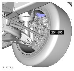
| 204-805 |
CAUTION:
Make sure the vehicle is on a flat level surface.
CAUTION:
Make sure the tire pressures are within specification.
CAUTION:
Make sure that only the manufacturers' recommended four wheel alignment equipment is used.
CAUTION:
Make sure the vehicles fuel tank is full, if not distribute extra weight evenly over the fuel tank area to represent a full tank of fuel.
CAUTION:
Make sure there are no heavy objects in the vehicle.
CAUTION:
Make sure the air suspension is set to NORMAL ride height.
CAUTION:
Make sure the steering is in the straight ahead position.
CAUTION:
Make sure the slip plates (turntables) are free to move before adjusting the geometry.
NOTE:
This procedure can be used for vehicles with either air or coil spring suspension.
- Check the tie rod ends, suspension joints, wheel bearings and wheels and tires for damage, wear and free play.
- Adjust or repair any worn, damaged or incorrectly adjusted components.
- Check and adjust tire pressures.
- Position the vehicle on a calibrated, level, vehicle lift.
- Release the vehicle parking brake.
- Vehicles with dynamic suspension: Using the approved diagnostic tool, check the air suspension control module for fault codes and clear as required.
- Vehicles with dynamic suspension: Using the diagnostic tool, set vehicle to 'Geometry Set Mode', using the instructions below. Putting the vehicle into this mode will make sure that the ride heights are controlled more accurately.
- Select the 'Configuration' tab
- Select 'Set up and Configure'.
- Select 'Air Suspension'.
- Select 'Suspension Geometry Set Up'.
- Select 'Tight Tolerance Mode'.
- Follow the on-screen instructions until the set up process has finished.
- Using only four wheel alignment equipment approved by Land Rover, check and adjust the wheel alignment.
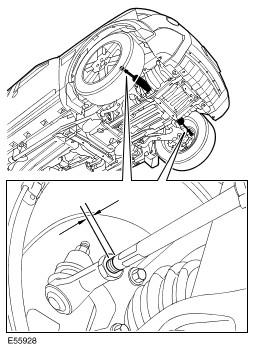
- Adjust the rear bump steer.
- Adjust the rear camber.
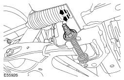
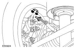
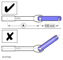
- Install the special tool and a suitable socket to the rear camber adjusting bolt retaining nut.
- A = Effective length of the torque wrench, measured in mm.
- Torque wrench setting (Nm) = (133xA)/(A+100)
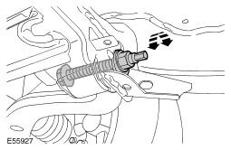
- Using the special tool, a suitable extension bar and a torque wrench, fully tighten the camber adjusting bolt retaining nut.
- Adjust the rear toe.
- Adjust the front camber.
- Adjust the front castor.
- Loosen the lower arm rear castor adjusting bolt.
- Rotate the castor adjusting bolt until the correct value is obtained.
- Tighten the lower arm rear castor adjusting bolt.
- Repeat the above procedure for the other side.
- Repeat the castor measurement.
- Repeat the above procedure until both castors achieve the correct value.
- Tighten the lower arm rear castor adjusting bolts to 275 Nm (203 lb.ft).
- Align the steering to straight ahead.
- Measure the length of the exposed thread on each track rod.
- If the exposed thread lengths differ by more than two millimetres:
- Stage one: Loosen one track rod end locking nut.
- Stage two: Rotate the track rod until the lengths of the exposed threads on both track rods are equal.
- Stage three: Tighten the track rod end locking nut.
- Stage four: Rotate the steering wheel until both front toe measurements are equal.
- Adjust the front toe.
- Vehicles with dynamic suspension: Using the diagnostic tool, return the vehicle to 'Normal Mode'.
- Select the 'Configuration' tab
- Select 'Set up and Configure'.
- Select 'Air Suspension'.
- Select 'Suspension Geometry Set Up'.
- Select 'Normal Mode'.
- Follow the on-screen instructions until the normal mode process has finished.
- Calibrate the steering angle sensor using the diagnostic tool.
NOTE:
If rear camber adjustment is required, loosen the rear camber adjustment bolts enough to allow adjustment before starting any other wheel alignment adjustments. Do not fully loosen the rear camber adjustment bolts.
CAUTION:
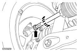
Make sure the toe link anti-rotation tang is fully seated in the integrated body frame before tightening the toe link retaining nut. Failure to follow this instruction will result in damage to the toe link or integrated body frame.
NOTE:
This step is only required if the toe links have been removed or replaced.
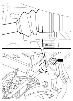
NOTE:
The torque wrench must be installed in a direct line with the special tool, as shown.
NOTE:
Calculate the torque wrench setting using the formula below.
NOTE:
Key to letters:
Formula:
Formula:
CAUTION:
Make sure the slip plates (turntables) are free to move before adjusting the geometry.