TRUSTMARK Authoring Standards (TAS) Removal And Installation Procedures
A TAS removal and installation procedure uses a sequence of color illustrations to indicate the order to be followed when removing/disassembling or installing/assembling a component.
Many of the TAS procedures will have the installation information within the removal steps. These procedures will have the following note at the beginning of the procedure:
Items such as O-ring seals, gaskets, seals, self-locking nuts and bolts are to be discarded and new components installed unless otherwise stated within the procedure. Coated nuts or bolts are to be reused, unless damaged or otherwise stated within the procedure.
Specification procedures will contain all technical data that are not part of a repair procedure.
TAS Graphics
Colors used in the graphic are as follows:
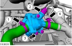
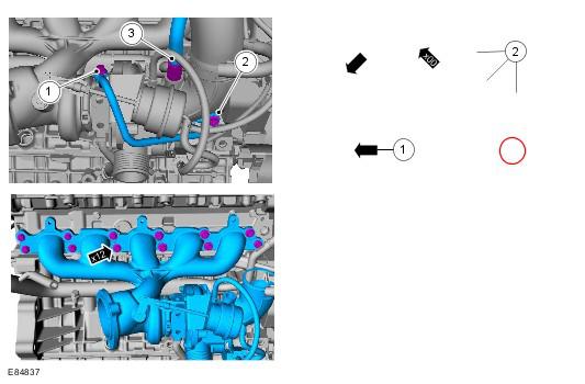
- Blue - Indicates the target item, item to be removed/installed or disassembled/assembled
- Green and Brown - Indicates a secondary item that needs to be detached, removed/installed or disassembled/assembled prior to the target item
- Magenta - Indicates electrical connectors and fasteners such as nuts, bolts, clamps or clips
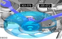
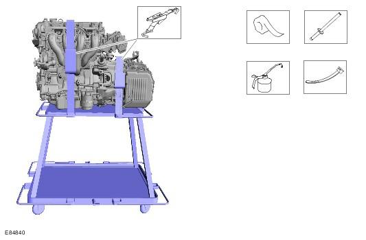
- Pale Blue - is for the special tool(s) and general equipment.
There may be multiple steps assigned to one illustration.
Numbered pointers are used to indicate the number of electrical connectors and fasteners such as nuts, bolts, clamps or clips.
Items in the illustration can be transparent or use cutouts to show hidden detail(s).
TAS Symbols
Symbols are used inside the graphics and in the text area to enhance the information display. The following paragraphs describe the various types and categories of symbols.
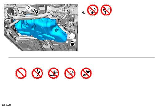
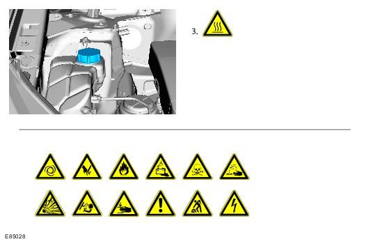
Prohibition symbols advise on prohibited actions to either avoid damage or health and safety related risks.
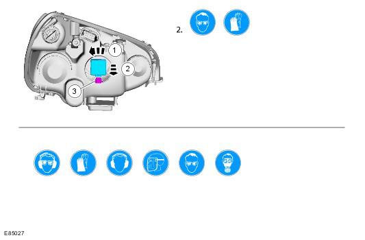
Health and Safety symbols recommend the use of particular protection equipment to avoid or at least reduce the risk or severity of possible injuries.
Warning symbols are used to indicate potential risks resulting from a certain component or area.
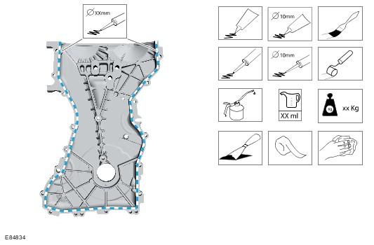
Instruction symbols are used to apply sealer, lubricant, weight, tape or cleaning detergent to a component.
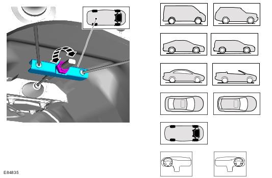
Location symbols are used to show the location of a component or system within the vehicle.
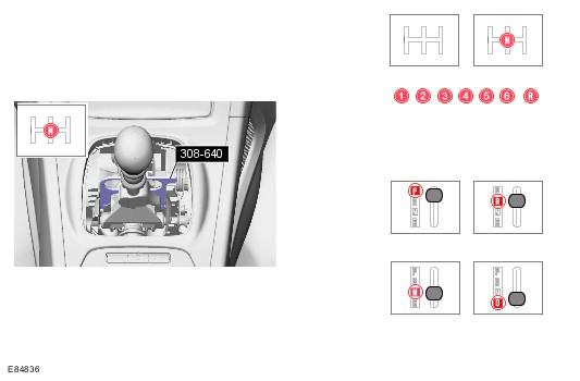
Gearshift lever or selector lever position symbols are used to show which gearshift lever or selector lever position is to be set.
Pointer symbols are used to draw the attention to components and give special instructions such as a required sequence or number of components. The number of components is reflected by the value inside the luty arrow. A sequence number is located inside the circle. Numbers inside circles are also used to allocate special information such as tightening torques or chemicals to a particular component.
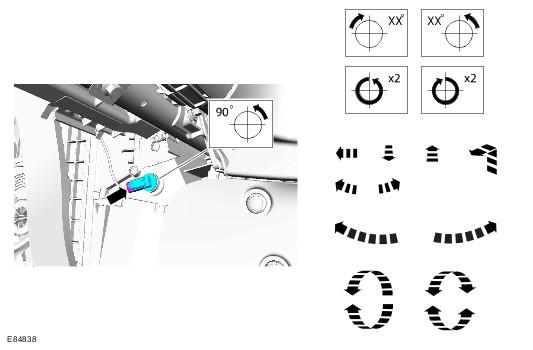
Movement arrows are used to show three dimensional or rotational movements. These movements can include specific values inside the symbol if required.
Standard tool symbols recommend the use of certain standard tools. These tools can include dimension values if required.
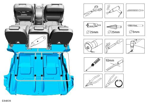
The following graphic illustrates a set of symbols that are used to provide detailed information on where to apply a material.
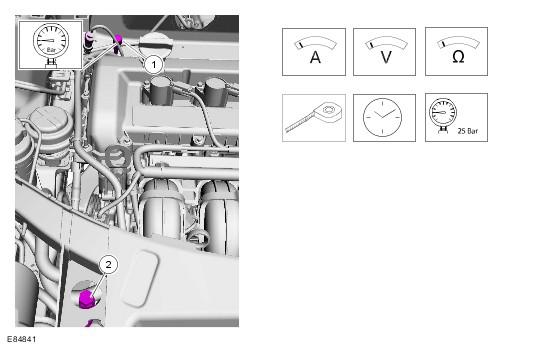
Measurement symbols provide detailed information on where to carry out a specific measurement. These symbols can include specific values if required.
Special Tools and Torque Figure(s)
Special tools will be shown with the tool number in the illustration. The special tool number(s), general equipment, material(s) and torque figure(s) used for the procedure step will be shown in the text column.