Electronic Throttle
The electric throttle controls the air flow into the engine. In addition to the normal engine power control function, the electric throttle allows the cruise control, idle speed control and engine speed limiting functions to be performed without the need for additional hardware.
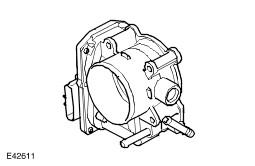
The electric throttle consists of a throttle body which incorporates a throttle plate driven by a DC motor via reduction gears. A return spring biases the throttle plate in the closed direction.
Operation of the DC motor is controlled by the ECM, which outputs two Pulse Width Modulated (PWM) signals to an H bridge drive circuit in the motor. The ECM varies the speed and direction of the motor by varying the duty cycle of the PWM signals.
To enable closed loop control, the position of the throttle plate is supplied to the ECM by two feedback Hall effect sensors in the throttle body. The feedback sensors have a common 5 volt supply and a common ground connection from the ECM, and produce separate linear signal voltages to the ECM proportional to the position of the throttle plate. The ECM uses the signal from feedback sensor 1 as the primary signal of throttle plate position, and the signal from feedback sensor 2 for plausibility checks.
- The signal from feedback sensor 1 varies between 0.5 volt (0% throttle open) and 4.5 volts (100% throttle open)
- The signal from feedback sensor 2 varies between 4.5 volts (0% throttle open) and 0.5 volt (100% throttle open)
While the ignition is on, the ECM continuously monitors the two feedback sensors for short and open circuits and checks the feedback sensor signals, against each other and the inputs from the Accelerator Pedal Position (APP) sensor, for plausibility. If a fault is detected in the feedback sensor signals or the DC motor, the ECM:
- Stores a related fault code in memory.
- Illuminates the SERVICE ENGINE warning lamp in the instrument pack.
- Adopts a throttle limp home mode or disables throttle control, depending on the nature of the fault.
The throttle limp home mode adopted depends on the nature of the fault:
- If there is a fault with one feedback sensor, or the throttle position controller in the ECM, the ECM limits vehicle acceleration by limiting throttle plate opening.
- If there is a fault with both feedback sensors, the ECM uses fuel injection cut-off to limit engine speed to 1300 rev/min maximum.
| Pin No | Description | Input/ Output |
|---|---|---|
| 1 | Throttle position 1 | Input |
| 2 | 5 volt reference voltage | Input |
| 3 | Throttle position 2 | Input |
| 4 | Sensor Ground | - |
| 5 | Throttle + | Input |
| 6 | Throttle - | Input |