Fuel Pump And Sender Unit: Removal
WARNING:
After carrying out repairs, the fuel system must be checked visually for leaks. Failure to follow this instruction may result in personal injury.
WARNING:
After the fuel tank drain is complete always fit the sealing covers over the drain ports. Failure to do so will mean that fuel vapor can escape.
WARNING:
This procedure involves fuel handling. Be prepared for fuel spillage at all times and always observe fuel handling precautions. Failure to follow these instructions may result in personal injury.
CAUTION:
Make sure the workshop area in which the vehicle is being worked on is as clean and as dust free as possible. Foreign matter from work on clutches, brakes or from machining or welding operations can contaminate the fuel system and may result in later malfunction.
NOTE:
Removal steps in this procedure may contain installation details.
- Refer to Petrol and Petrol-Ethanol Fuel Systems Health and Safety Precautions information.
- Disconnect the battery ground cable. Refer to Specifications information.
- Raise and support the vehicle.
- Refer to Fuel Tank Draining information.
- Torque:
Bolts 6 Nm
Nuts 2 Nm
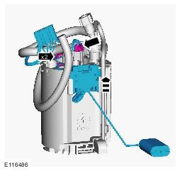
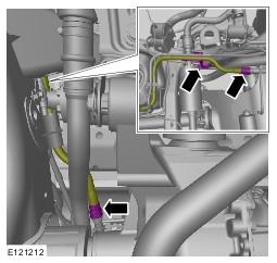
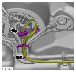
- Remove the tamper proof cover.
- See figure.
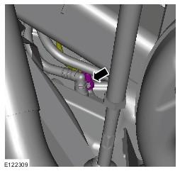
- See figure.
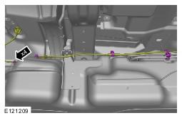
- See figure.
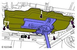
- See figure.
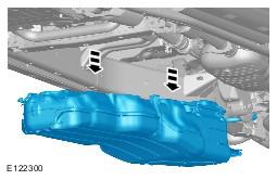
- Using a suitable transmission jack, lower the fuel tank sufficiently only to access the top of the fuel tank.
General Equipment: Transmission jack
Torque: 45
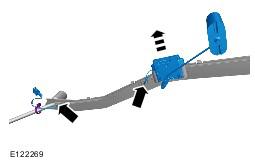
- See figure.
- With assistance, remove the fuel tank.
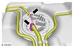
- See figure.
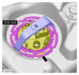
-
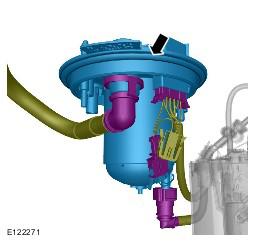
- Locking Ring, Fuel Tank (310-123)
- See figure.
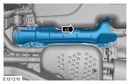
- See figure.
- See figure.
- See figure.
- See figure.
WARNING:
Make sure to support the vehicle with axle stands.
NOTE:
Discard the retaining clip.
CAUTION:
Make sure that all openings are sealed. Use new blanking caps.
CAUTION:
Make sure that all openings are sealed. Use new blanking caps.
CAUTION:
Be prepared to collect escaping fluids.
CAUTION:
Make sure that all openings are sealed. Use new blanking caps.
NOTE:
Transmission support heat shield shown removed for clarity.

WARNING:
Secure the component to the transmission jack.
CAUTION:
Do not lower the fuel tank more than 250 mm.
NOTE:
Note the orientation of the two rear retaining bolts and washers.
CAUTION:
Position the breather hose and vent hose through the vehicle body during the fuel tank removal operation.
NOTE:
Do not disassemble further if the component is removed for access only.
CAUTION:
Make sure that all openings are sealed. Use new blanking caps.
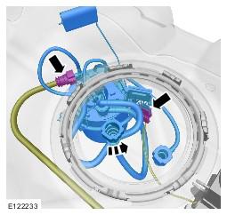
NOTE:
Note the position of the locating tang.
CAUTION:
Be prepared to collect escaping fuel.
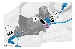
NOTE:
Remove and discard the O-ring seal.
CAUTION:
Take extra care not to damage the fuel tank level sensor float and arm.
NOTE:
Some variation in the illustrations may occur, but the essential information is always correct.
CAUTION:
Take extra care not to damage the fuel tank level sensor float and arm.
CAUTION:
Take extra care not to damage the fuel tank level sensor float and arm.