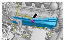
Fuel Rail LH: Installation
- Install new O-ring seals.
- Install new Teflon seals.
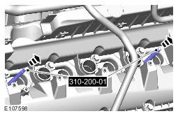
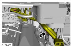
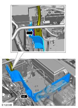
- See figure
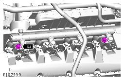
- See figure
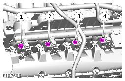
- See figure
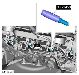
- See figure
- Torque: 20
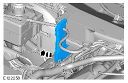
- See figure
- Torque: 20
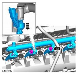
- Torque:
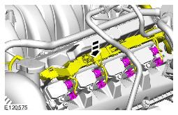
- Bolt 2 30 Nm
- Bolt 3 30 Nm
- Bolt 1 30 Nm
- Bolt 4 30 Nm
- Torque: 20
- Torque: 7
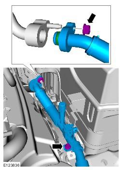
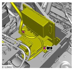
- See figure
- See figure
- Torque
- Unions 21 Nm
- Bolts 8 Nm
- Torque: 21
- Install new O-ring seals.
Torque: 12
- Install new O-ring seals.
Torque: 12
- Install new O-ring seals.
Torque: 12
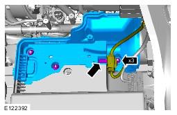
- Torque: 12
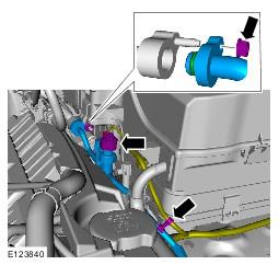
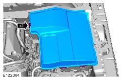
- See figure
- Refer to Battery information.
- See figure
- Torque: 10
- Refer to Evaporative Emission Canister Purge Valve information.
- See figure
- See figure
- See figure
- Refer to Air Cleaner Outlet Pipe T-Connector information.
- Refer to Air Conditioning (A/C) System Recovery, Evacuation and Charging information.
- Refer to Engine Cover - V8 5.0L Petrol information.
- Connect the battery ground cable. Refer to Specifications information.
All vehicles
CAUTION:
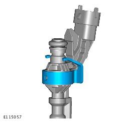
If the original fuel injector is being installed, the original fuel injector clamp must installed with the fuel injector it was removed with.
CAUTION:
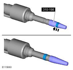
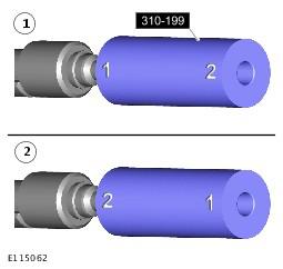
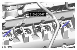
If a new cylinder head has been installed then the special tool 310-200-02 without the thread must be used to install the fuel rail.
CAUTION:
Make sure that the area around the open fuel injector ports are clean and free of foreign material and lubricant prior to installing the fuel injector.
CAUTION:
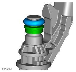
When installing the fuel injector(s), make sure that the Teflon seal is clean and free of foreign material and lubricant.
CAUTION:
If new fuel injectors are installed, a new injector clamp must be installed.
CAUTION:
Make sure that the fuel injector is aligned and installed into the fuel rail correctly, as noted in the removal step.
CAUTION:
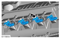
Tighten the fuel rail retaining bolts a turn at a time until the correct torque is achieved.
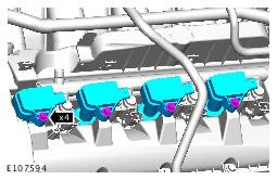
NOTE:
Lubricate the fuel injector O-ring seals with clean engine oil.
NOTE:
Tighten the bolts in the indicated sequence.
NOTE:
RH illustration shown, LH is similar.
CAUTION:
Lubricate only the union threads with clean engine oil.
NOTE:
Do not tighten at this stage.
NOTE:
Remove and discard the blanking caps.
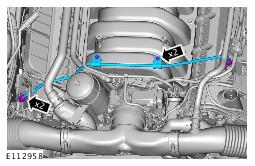
Right-hand drive vehicles
Left-hand drive vehicles
NOTE:
Right-hand shown, left-hand similar.
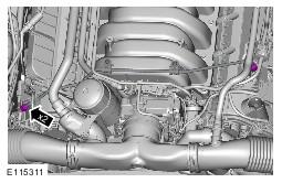
NOTE:
Right-hand shown, left-hand similar.
All vehicles
CAUTION:
Be prepared to collect escaping fluids.