Control Diagram
NOTE:
A
= Hardwired; N
= Medium Speed CAN Bus; O
= LIN Bus
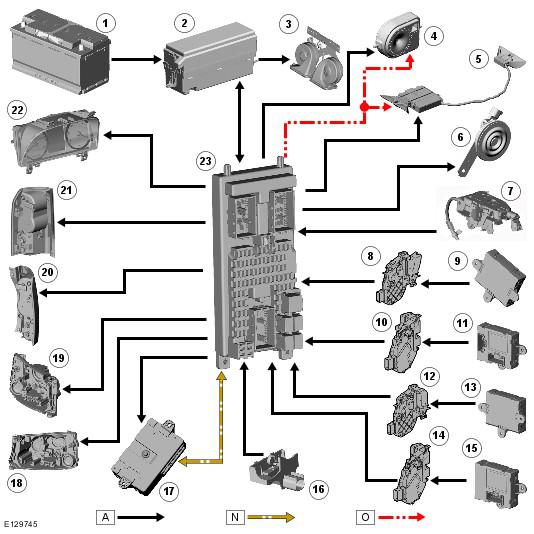
| Item Number | Description |
|---|---|
| 1 | Battery |
| 2 | Engine junction box |
| 3 | Horns |
| 4 | Battery backed-up sounder with integrated inclination sensor (if fitted) |
| 5 | Interior motion sensor |
| 6 | Passive sounder (if fitted) |
| 7 | Upper tailgate latch |
| 8 | Driver door latch |
| 9 | Driver door module |
| 10 | Passenger door latch |
| 11 | Passenger door module |
| 12 | Rear door latch |
| 13 | Rear door module |
| 14 | Rear door latch |
| 15 | Rear door module |
| 16 | Hood ajar switch |
| 17 | Keyless vehicle module |
| 18 | Left-hand front lamp (indicator) |
| 19 | Right-hand front lamp (indicator) |
| 20 | Left-hand tail lamp (indicator) |
| 21 | Right-hand tail lamp (indicator) |
| 22 | Instrument cluster |
| 23 | CJB |