Abs Module
The anti-lock brake system (ABS) module controls the brake functions using the hydraulic control unit (HCU) to modulate hydraulic pressure to the individual wheel brakes.
The anti-lock brake system (ABS) module is attached to the hydraulic control unit (HCU), in the plenum box on the driver side of the engine compartment. A 46 pin connector provides the electrical interface between the anti-lock brake system (ABS) module and the vehicle wiring.
ABS Module Harness Connector C0506
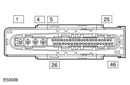
ABS Module Harness Connector C0506 Pin Details
| Pin No. | Description | Input/Output |
|---|---|---|
| 1 | Ground | Output |
| 2 | Battery power supply | Input |
| 3 | Battery power supply | Input |
| 4 | Ground | Output |
| 5 | Front left wheel speed sensor signal | Input |
| 6 | Rear left wheel speed sensor power supply | Output |
| 7 | Rear right wheel speed sensor power supply | Output |
| 8 | Rear right wheel speed sensor signal | Input |
| 9 | Front right wheel speed sensor power supply | Output |
| 10 | Front right wheel speed sensor signal | Input |
| 11 to 13 | Not used | - |
| 14 | High speed controller area network (CAN) bus low | Input/Output |
| 15 | Yaw rate and lateral acceleration sensor ground | Input |
| 16 | Yaw rate signal | Input |
| 17 | Not used | - |
| 18 | Yaw rate and lateral acceleration sensor reference | Input |
| 19 | Not used | - |
| 20 | Lateral acceleration signal | Input |
| 21 | Not used | - |
| 22 | HDC relay | Output |
| 23 to 25 | Not used | - |
| 26 | Front left wheel speed sensor power supply | Output |
| 27 | Rear left wheel speed sensor signal | Input |
| 28 | Ignition power supply | Input |
| 29 | Not used | - |
| 30 | Stoplamp switch BLS contacts | Input |
| 31 | DSC switch | Input |
| 32 | Not used | - |
| 33 | Road speed signal | Output |
| 34 | Not used | - |
| 35 | High speed controller area network (CAN) bus high | Input/Output |
| 36 | HDC switch | Input |
| 37 | Yaw rate and lateral acceleration sensor test | Output |
| 38 to 40 | Not used | - |
| 41 | Stoplamp switch BS contacts | Input |
| 42 to 46 | Not used | - |