Headlamp Assembly: Notes
| Item Number | Description |
|---|---|
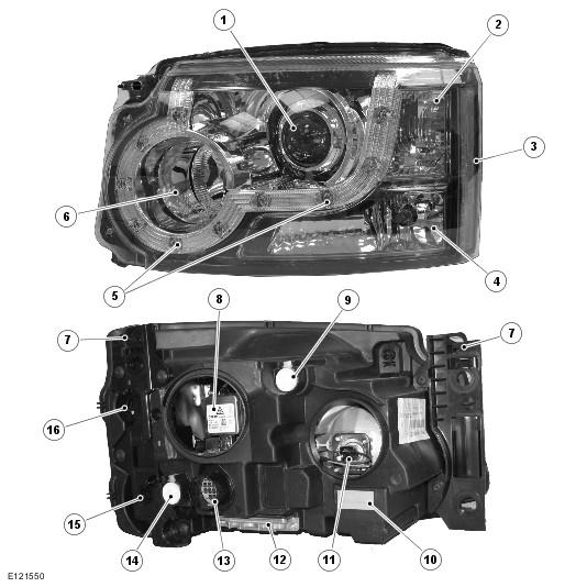
| 1 | Low beam headlamp |
| 2 | Turn signal indicator lamp |
| 3 | Side marker lamp (NAS only) |
| 4 | Side lamp (halogen headlamps), cornering lamp (Xenon headlamps) or cornering/static bending lamp (AFS headlamps) |
| 5 | Side lamp LED's (xenon headlamps only) |
| 6 | High beam halogen 'fill-in' headlamp |
| 7 | Locking plate |
| 8 | Low beam halogen bulb (halogen headlamps) or xenon bulb (xenon headlamps) |
| 9 | Vertical adjuster |
| 10 | Waterproof breather |
| 11 | High beam 'fill-in' lamp bulb |
| 12 | Xenon control module (not fitted to halogen headlamps) |
| 13 | Electrical connector |
| 14 | Horizontal adjuster |
| 15 | Side lamp or cornering/static bending lamp cover (hidden) |
| 16 | Turn signal indicator lamp access cover (hidden) |
Three types of headlamp are available; Halogen, Xenon or Xenon with Adaptive Front lighting System (AFS). The headlamps share a common, clear lens.
The headlamps are located behind the front carrier assembly. Each headlamp is secured to the front carrier assembly with two locking plates. The locking plate slides in grooves in the rear of the headlamp and two holes in each plate locate on pins on the carrier. Each locking plate is pressed down to lock the pins in the locking plate holes. The locking plates allow removal of the headlamp from the carrier for bulb changing without the requirement for special tools.
The rear of the headlamp unit has removable access panels which allow access to the bulbs for replacement. A large rubber cover allows access to the low/high beam bulb on both halogen and xenon headlamps. Another removable rubber cover provides access to the high beam only halogen bulb which is retained by a push fit. A smaller cover can also be rotated anti-clockwise to provide access to the turn signal indicator lamp bulb. The indicator bulb is a PH24WY orange bulb and is clipped into the cover and is pulled to remove. Below this cover is a removable cover which provides access to the side lamp bulb on halogen headlamps or the cornering lamp/static bending lamp bulb on xenon headlamps and the side marker lamp bulb on NAS models. On xenon headlamps the side lamps are LED's and therefore are not serviceable components.
The headlamps have two adjustment screws on the rear which allow for the manual setting of the vertical and horizontal alignment. On NAS vehicles the headlamp is regarded as Visual Optically Left (VOL) aiming. The adjustment screws have to be turned equal amounts to maintain the correlation in the vertical axis only. There is no horizontal adjustment. Refer to the Service Repair Procedures information for headlamp alignment data.
Each headlamp has an integral sixteen pin connector which provides inputs and outputs for the various functions of the headlamp assembly. The usage of the pins differs between model variants, refer to the Electrical Reference Library (ERL) for pin details.
The low beam headlamps are switched on when the ignition is in ignition mode 6 and:
- the lighting control switch is in the headlamp position
- the lighting control switch is in the AUTO position and a 'lights on' signal is received by the CJB from the rain/light sensor.
The low beam headlamps can also be operated by the headlamp delay feature.
The high beam headlamps are switched on when the ignition is in ignition mode 6 and:
- the low beam headlamps are selected on in the headlamp position or activated via the AUTO feature
- The left hand steering column multifunction switch is pushed forward away from the driver
- The auto high beam system (if fitted) has switched on the high beam headlamps.
The high beam headlamps will be switched off when:
- The left hand steering column multifunction switch is moved rearward towards the driver
- The low beam headlamps are switched off
- The ignition mode is changed to the accessory mode 4 or ignition off
- The auto high beam system (if fitted) has switched off the high beam headlamps.