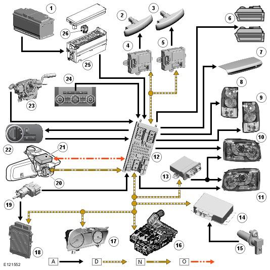
Control Diagram
| Item Number | Description |
|---|---|
| 1 | Battery |
| 2 | LH side repeater turn signal indicator |
| 3 | RH side repeater turn signal indicator |
| 4 | LH Door module |
| 5 | RH Door module |
| 6 | License plate lamps (2 off) |
| 7 | High mounted stop lamp |
| 8 | LH rear lamp assembly |
| 9 | RH rear lamp assembly |
| 10 | LH headlamp assembly |
| 11 | RH headlamp assembly |
| 12 | Central Junction Box (CJB) |
| 13 | AFS control module |
| 14 | Transfer box control module |
| 15 | Transmission reverse switch (manual transmission only) |
| 16 | Transmission Control Module (TCM) (Automatic transmission only) |
| 17 | Instrument cluster |
| 18 | Engine Control Module (ECM) |
| 19 | Stop lamp switch |
| 20 | Auto high beam image sensor and control module |
| 21 | Rain/light sensor |
| 22 | Lighting control switch |
| 23 | LH steering column multifunction switch |
| 24 | Hazard warning indicators switch |
| 25 | Engine Junction Box (EJB) |
| 26 | Auto high beam relay |
NOTE:
A
= Hardwired; D
= High Speed CAN Bus; N
= Medium speed CAN bus; O
= LIN Bus