Repair Procedure
CAUTION:
Do not use crimping pliers, insulation strippers, butt splice connectors, heat shrink sleeves or pre-terminated wiring harness(s) that are not supplied with the Jaguar wiring harness repair kit. Each part has been designed to be used only with the other parts in this wiring harness repair kit.
CAUTION:
Where the repair procedure indicates that a glue lined heat shrink sleeve should be applied, apply sufficient heat to the glue lined heat shrink to melt the glue in order to provide a water tight seal. Do not
over heat the glue lined heat shrink sleeve so that the wiring harness insulation becomes damaged.
It is not correct to make more than five repair joints on the wiring harness to any electrical connector and if more damage is found at the same electrical connector then a new wiring harness must be installed.
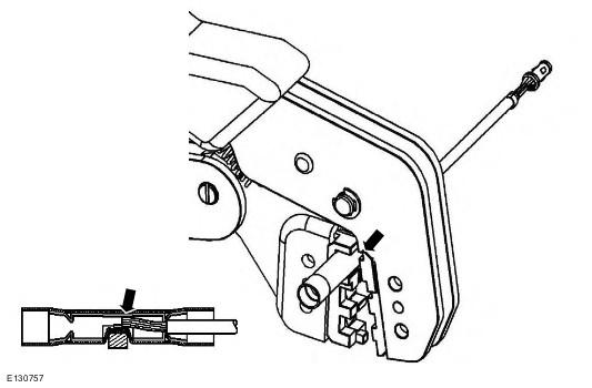
- Remove the faulty terminal from the electrical connector using the extractor tool and correct tip. Make sure that any anti-backout device is released before trying to remove the terminal.
- Select the correct size and type of pre-terminated wiring harness and butt splice connector from the wiring harness repair kit.
- Using the wire cutter on the stripping tool, cut the pre-terminated wiring harness and the harness cable to the required length.
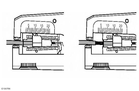
- From the Relationship Table, find the correct length of insulation to be stripped from the pre-terminated wiring harness and set the adjustable cable length stop to the correct length. Place the pre-terminated wiring harness in the wire stripper and remove the insulation.
- Put the cable identification sleeve(s) on to the wiring harness with the main cable colour nearest to the terminal.
- During this next step do not overtighten. Place the selected butt splice connector in the crimping tool, matching the aperture and the butt connector colours. Make sure that the window indentation in the butt connector is resting over the guide bar on the lower jaw. Partially close the grip until the butt connector is securely held in the aperture. This will give support to the butt connector while the pre-terminated wiring harness is inserted into it.
- Insert the pre-terminated wiring harness into the butt connector and make sure that the wire is against the wire stop. Close the grip firmly, crimping the lead to the butt connector. When the handles have been completely closed the butt connector will be freed from the tool as the handles are released. If the handles have not been completely closed then the jaws will hold the butt connector and it cannot be removed from the tool until the crimp is fully made by closing the handles completely.
- Make sure that the harness cable has been squarely cut and the correct length of insulation removed. If more than one splice is needed the butt connectors must be not be crimped to the wiring harness at the same distance from the connector. The splices must be staggered to prevent a bulk of splices in the same area of the wiring harness.
- It is preferable to cover the butt splice joint with heat shrink sleeve. This is desirable not essential, except where the electrical connector is a sealed electrical connector. Use the smaller diameter sleeve for red and blue pre-terminated wiring harness(s) and the large diameter sleeve for the yellow pre-terminated wiring harness(s). It is advisable to place the heat shrink over the completed joint but in some instances the sleeve will not pass over the terminal. Check, and if required, place the correct size sleeve onto the harness cable or pre-terminated wiring harness before crimping the butt splice to the wiring harness.
- Place the harness cable into the butt splice with the splice window over the guide bar. Make sure that the cable harness wire is against the stop in the butt splice, crimp the butt splice connector to the wiring harness.
- Gently pull the harness cables each side of the butt splice to make sure that a secure joint has been made.
- Using a suitable heat source, shrink the sleeve over the butt splice.
- If further pre-terminated wiring harness(s) are to be installed to the same electrical connector, make sure that the lead is cut at a different length to the previous joint. This makes sure that the splices will, where possible, be staggered on the wiring harness and prevent a bulk of splices in one area.
- When all of the splices have been made, fit the terminal(s) to the electrical connector, taking care that the terminals are correctly orientated.
- Install the wiring harness cover and secure with adhesive electrical tape. Do not cover the wiring harness right to the electrical connector as the terminals must have a little movement and not be firmly bound to the electrical connector or wiring harness. Make sure that the cable identification sleeve(s) are showing at the wiring harness electrical connector.
CAUTION:
: A number of electrical connector terminals are gold plated or gold flashed. When defective, they must be installed with a gold pre-terminated wiring harness(s) from the wiring harness repair kit. It is not always easy to identify the female as gold but the male pins are visually easier, therefore always check both male and female terminals to identify those which are gold. Under no circumstances are gold and tin terminals to be mixed as this will lead to early failure of the electrical contact.
NOTE:
Never use a harness lead with a smaller diameter than the original harness lead.
NOTE:
See illustration: Stripping Insulation
NOTE:
See illustration: Spice Correctly Located
WARNING:
Do not use a naked flame in areas where fuel or oil have been spilt. Clean the area of residual oil and fuel and wait until the fuel spill has fully evaporated.
CAUTION:
When using a heat source make sure that it is localised and causes no damage to surrounding materials.
CAUTION:
Where the repair procedure indicates that a glue lined heat shrink sleeve should be applied, apply sufficient heat to the glue lined heat shrink to melt the glue in order to provide a water tight seal. Do not
over heat the glue lined heat shrink sleeve so that the wiring harness insulation becomes damaged.
Stripping Insulation
Splice Correctly Located