Right Hand Parking Aid Camera Wiring Harness: Removal
CAUTION:
Make sure that the camera overlay wiring harness is not bent excessively during this procedure. Failure to follow this instruction may result in damage to the harness.
- Remove the LH front seat. Refer to: Front Seat information.
- Repeat procedure for the other side.
- Remove the floor console. Refer to: Floor Console information.
- Remove the LH scuff plate trim panel. Refer to: Scuff Plate Trim Panel information.
- Repeat procedure for the other side.
- Release the wiring harness cover.
- Release the 3 clips.
- Repeat procedure for the other side.
- Remove the RH cowl side trim panel. Refer to: Cowl Side Trim Panel information.
- Remove the accelerator pedal assembly. information.
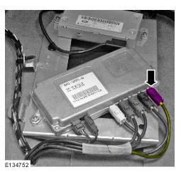
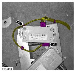
- Remove the dynamic response module.
- Remove the 2 bolts.
- Disconnect the 2 electrical connectors.
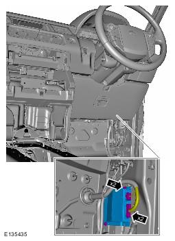
- Disconnect the 2 electrical connectors.
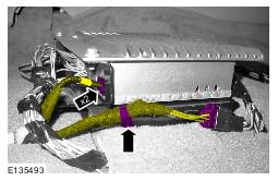
- Release the 3 clips.
- Disconnect the 2 electrical connectors.
- Release the clip.
- Release the wiring harness cover.
- Reposition the floor covering for access.
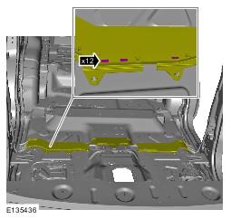
- Using a suitable tool, carefully cut though the wiring harness cover retaining tape.
- Release the 12 clips.
- Release the gaiter.
- Remove the wiring harness cover.
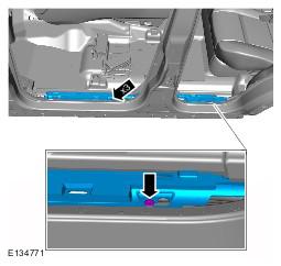
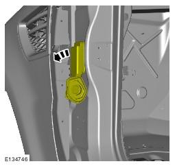
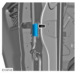
- Release the 4 clips.
- Disconnect the electrical connector.
- Release the electrical connector bracket.
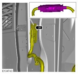
- Release the 6 clips.
- Disconnect the electrical connector.
NOTE:
Door shown removed for clarity.
NOTE:
Left-hand shown, right-hand similar.
NOTE:
Left-hand shown, right-hand similar.
NOTE:
Left-hand shown, right-hand similar.