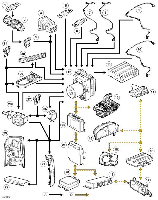
Anti-Lock Control Diagram
NOTE:
A = Hardwired connections; D = High speed CAN bus
| Item Number | Description |
|---|---|
| 1 | Fble link 11E, battery junction box (BJB)usible link 11E, |
| 2 | Ignition switch |
| 3 | Fuse 37P, CJB |
| 4 | Yaw rate and lateral acceleration sensor |
| 5 | Fusible link 9E, BJB |
| 6 | Fusible link 23E, BJB |
| 7 | Front wheel speed sensor |
| 8 | Front wheel speed sensor |
| 9 | Rear wheel speed sensor |
| 10 | Rear wheel speed sensor |
| 11 | Navigation computer |
| 12 | ABS module |
| 13 | Transmission control module |
| 14 | Diagnostic socket |
| 15 | Instrument cluster |
| 16 | Air suspension control module |
| 17 | Parking brake module |
| 18 | Steering angle sensor |
| 19 | Rear differential control module |
| 20 | Restraints control module |
| 21 | Left stoplamp |
| 22 | Center stoplamp |
| 23 | Right stoplamp |
| 24 | ECM |
| 25 | Transfer box control module |
| 26 | HDC relay (non-serviceable, integrated into CJB) |
| 27 | Fuse 15P, CJB |
| 28 | Stoplamp switch |
| 29 | HDC switch |
| 30 | DSC switch |
| 31 | Fuse 66P, CJB |