Brake Pads - (Vehicles With: Standard Brakes): Installation
- Clean the brake caliper housing and anchor plate using brake cleaning fluid.
- Inspect the caliper piston and slide pin seals for damage.
- Check the slide pins for correct operation.
- Press the pistons into the caliper housing.
- Install the brake pads.
- Install the 2 clips.
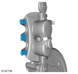
- Apply a suitable amount of the supplied grease to the caliper, as illustrated.
- Install the brake pads.
- Rotate the brake caliper downwards.
- Tighten the bolt to 35 Nm (26 lb.ft).
- Repeat the above procedure for the other side.
- LH side front: Connect the brake pad wear indicator wiring harness electrical connection.
- Install the front LH fender splash shield. Refer to Fender Splash Shield information.
- LH side front: Connect the brake pad wear indicator wiring harness.
- Install the wheels and tires.
- Depress the brake pedal several times, check the fluid level in the brake fluid reservoir and top-up with brake fluid if necessary.
- Refer to Brake Pad Bedding-In information.
WARNING:
Do not use compressed air to clean brake components. Dust from friction materials can be harmful if inhaled.
CAUTION:
The brake caliper should move freely on both slide pins.
CAUTION:
If necessary, renew the components.
CAUTION:
Make sure that the plain slide pin is installed to the upper part of the caliper and the bushed slide pin is installed to the lower part.
CAUTION:
Check the brake fluid reservoir level before pushing the piston back, failure to follow this instruction may result in damage to the vehicle.
NOTE:
As the piston is pushed back into the caliper housing, the brake fluid level in the reservoir will rise. Do not allow the reservoir to overflow.
NOTE:
Make sure that the plain clip is installed to the bottom part of the caliper and the rubber coated clip is installed to the upper part.
NOTE:
Make sure the brake pads are installed in the correct orientation.
NOTE:
This step is only required if a new wear indicator harness is installed.
NOTE:
This step is only required if a new wear indicator harness is installed.
NOTE:
Tighten the wheel nuts in the sequence shown: