Axle Assembly: Removal
NOTE:
Some variation in the illustrations may occur, but the essential information is always correct.
- Raise and support the vehicle.
- Remove the front wheels and tires.
- Remove the axle tube. See Axle Tube .
- Remove the LH splash shield.
- Remove the 4 clips.
- Release the LH stabilizer bar link.
- Remove and discard the nut.
- Release the LH brake hose bracket from the wheel knuckle.
- Remove the bolt.
- Using the special tool, release the LH tie-rod end ball joint from the wheel knuckle.
- Remove and discard the nut.
- Using the special tool, release the LH upper arm ball joint.
- Remove and discard the nut.
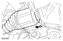
- Release the LH halfshaft from the axle assembly.
- Remove and discard the snap ring.
- Using a suitable tie strap, support the LH halfshaft.
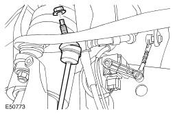
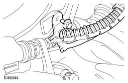
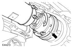
- Release the driveshaft from the front axle drive flange.
- Remove the 6 Torx bolts and washers, discard the bolts.
- Using a suitable tie strap, secure the driveshaft end plate.
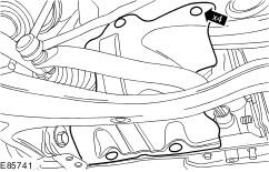
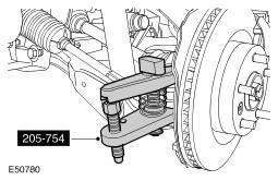
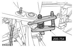
- Remove the stabilizer bar bushing.
- Remove the 3 bolts.
- Remove the clamp.
- Remove the stabilizer bar bushing.
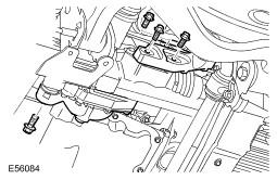
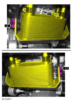
- Release the fuel cooler.
- Remove the bolt.
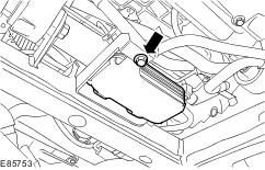
- Release the automatic transmission fluid cooler.
- Remove the 4 bolts.
- Remove the transmission fluid cooler mounting bracket.
- Release the transmission fluid cooler pipe bracket.
- Remove the nut.
- Remove the 3 bolts.
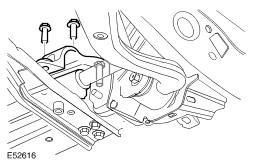
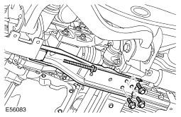
- Remove the front axle crossmember.
- Remove the 4 bolts.
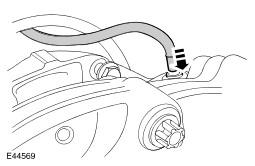
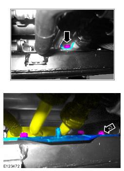
- Disconnect the breather line.
- Release the clip.
- Using a transmission jack, support the front axle assembly.
- With assistance, remove the front axle assembly.
- Remove and discard the 3 axle assembly rear mounting bolts.
- Remove the front axle assembly front mounting bolt.
All vehicles
WARNING:
Make sure to support the vehicle with axle stands.
CAUTION:
Make sure the ball joint seal is not damaged. A damaged seal will lead to the premature failure of the joint.
CAUTION:
Make sure the ball joint seal is not damaged. A damaged seal will lead to the premature failure of the joint.
CAUTION:
The lower arm ball joint can be damaged by excessive articulation. The wheel knuckle must be fully supported at all times. Do not allow the wheel knuckle to hang on the lower arm. Failure to follow this instruction will result in damage to vehicle.
CAUTION:
Mark the position of the driveshaft flange in relation to the drive pinion flange.
CAUTION:
To avoid damage to the joint or gaiter, do not allow the driveshaft to hang.
Vehicles with Active Stabilization
Vehicles with diesel engine
Vehicles with 5.0L engine
All vehicles
CAUTION:
Before the disconnection or removal of any components, make sure the area around joint faces and connections are clean. Plug any open connections to prevent contamination.