Open Rear Differential Assembly: Notes
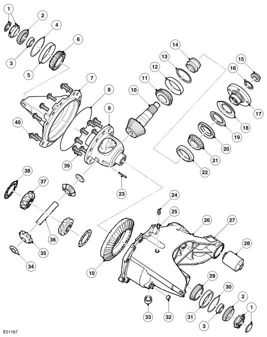
Open Rear Differential - Exploded View
| Item Number | Description |
|---|---|
| 1 | Cap |
| 2 | Seal |
| 3 | Bearing assembly, without race |
| 4 | Bearing pre-load spacer |
| 5 | Bearing |
| 6 | Roller bearing cup |
| 7 | Cover |
| 8 | Seal |
| 9 | Differential carrier |
| 10 | Gear and pinion assembly |
| 11 | Bearing |
| 12 | Roller bearing cup |
| 13 | Shim |
| 14 | Collapsible spacer |
| 15 | Pinion nut |
| 16 | Retainer |
| 17 | Flange |
| 18 | Outer deflector |
| 19 | Inner deflector |
| 20 | Oil seal |
| 21 | Bearing |
| 22 | Roller bearing cup |
| 23 | Roll pin |
| 24 | Breather cap |
| 25 | Breather |
| 26 | Case |
| 27 | Data location |
| 28 | Mounting bush |
| 29 | Bearing |
| 30 | Bearing pre-load spacer |
| 31 | Roller bearing cup |
| 32 | Plug |
| 33 | Drain plug |
| 34 | Thrust washer |
| 35 | Planet gears |
| 36 | Crosspin shaft |
| 37 | Sunwheel |
| 38 | Thrust washer |
| 39 | Bolt, 10 of |
| 40 | Bolt, 12 of |
The cast iron casing comprises two parts; a cover and a carrier. The carrier provides locations for all the internal components. The carrier is sealed to the cover via an O-ring seal and secured with twelve bolts. The cover and carrier have cast fins, which assist mobility. A breather tube is fitted to the top of the carrier. This allows a plastic tube to be fitted and routed to a high point under the vehicle body, preventing the ingress of water when the vehicle is wading.
The carrier contains an oil drain plug. The differential unit contains approximately 1.16 liters of oil from a dry fill. If oil is being replaced, a smaller quantity of oil will be required due to residual oil retained in the pinion housing.
The differential is a conventional design using a hypoid gear layout, similar to the front differential. The open rear differential is available in three ratios. V8 petrol engine vehicles use a differential with a final drive ratio of 3.73:1, V6 petrol engine vehicles use a differential with a final drive ratio of 3.73:1 and TdV6 engine vehicles use a final drive ratio of 3.54, for vehicles with automatic transmission and 3.07 for vehicles with manual transmission. Changing the number of teeth between the crown wheel drive gear and pinion gear changes the ratio.
The differential comprises a pinion shaft and hypoid pinion gear and a crown wheel drive gear with an integral cage, which houses two planet gears. Two sun wheels are also located in the cage and pass the rotational drive to the drive shafts.
The pinion shaft is mounted on two opposed taper roller bearings, with a collapsable spacer located between them. The spacer is used to hold the bearings in alignment and also collapses under the pressure applied to the pinion flanged nut. This allows the flanged nut to be tightened to a predetermined torque, which collapses the spacer, setting the correct bearing preload.
The pinion shaft has an externally splined outer end, which accepts and locates the input flange, which is retained by the pinion nut and retainer. The input flange has four threaded holes and mates with the rear drive shaft. Four bolts secure the rear drive shaft to the input flange. An oil seal is pressed into the pinion housing and seals the input flange to the pinion housing. The pinion shaft has a hypoid gear at its inner end, which mates with the crown wheel drive gear.
The crown wheel drive gear is located on the differential case and secured with ten screws. The differential case is mounted on taper roller bearings located in machined bores on each side of the pinion housing. Shims are retained in the casing behind the bearing cups, the shim thickness is selected to apply the correct bearing preload and hypoid backlash.
The differential carrier has a through hole, which provides location for the shaft. The shaft is supported by a sun gear and a needle roller bearing. The shaft is fitted with a snap ring at one end, which locates in a machined groove in the sun gear, locking the shaft in position.
The sun gears are located in pockets in the carrier cage and mesh with the planet gears. Spacers are fitted between the sun wheels and the carrier and set the correct mesh contact between the planet gears and the sun wheels. Each sun wheel has a machined bore with internal splines and machined groove near the splined end. The groove provides positive location for a snap ring fitted to the end of each output flange.
Each output shaft has a spline, which locates in each sun wheel. A snap ring fitted to the splined shaft locates in the groove the sun wheel bore and positively located the output shaft. Oil seals are pressed into each side of the pinion housing and seal the seal the output shaft.