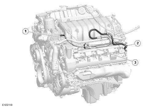
Purge Valve And Pipes
| Item Number | Description |
|---|---|
| 1 | Pipe to engine |
| 2 | Pipe from charcoal canister |
| 3 | Purge valve |
The purge valve is installed on a bracket attached to the left-hand (LH) cylinder head cover. The pipe to the engine from the purge valve is connected to the intake manifold (naturally aspirated vehicles), or supercharger (SC) front cover (supercharger (SC) vehicles), with a quick release connector. The pipe to the charcoal canister from the purge valve is installed between the left-hand (LH) cylinder head cover and ignition coil cover. From the rear of the left-hand (LH) cylinder head, the pipe then goes across the back of the engine, along the right-hand (RH) side of the transmission, along the fuel tank and rearwards of the tank to the charcoal canister.
The purge valve is a solenoid operated valve, which is closed when de-energized. The valve is controlled by the engine control module (ECM) and is operated when engine operating conditions are suitable for purging of the charcoal canister.
The purge valve is controlled by a pulse width modulation (PWM) signal at 10 Hz from the engine control module (ECM). At this frequency, the pulses of purge gas flow into the engine in an almost continuous flow. The valve operates between 0% and 99% duty or mark space ratio (% open time).
The atmospheric pressure at the air intake vent of the system is higher than the inlet manifold pressure under all throttled engine running conditions. It is this pressure differential across the system that causes the air to flow through the air intake of the purge system and in to the engine. The operation of the supercharger does not affect the purging process.
The engine control module (ECM) waits until the engine is running with a coolant temperature of 55 °C (131 °F) or above and closed loop fuel operational before the purging process is activated. Under these conditions the engine should be running smoothly with no warm up enrichment. The purge valve duty (and flow) is initially ramped slowly because the vapor concentration is unknown (a sudden increase in purge could cause the engine to stall or loss of AFR (air fuel ratio) control to occur). The concentration is then determined from the amount of adjustment that the closed loop fueling is required to make to achieve the target AFR. Once the concentration has been determined, the purge flow can be increased and the injected fuel can be proactively adjusted to compensate for the known purge vapor and the target AFR control is maintained.
When the purging process is active, fresh air is drawn into the charcoal canister via the atmospheric vent filter and, on NAS vehicles, the DMTL pump.