Engine Cooling: Operation
ENGINE COOLING FLOW DIAGRAM
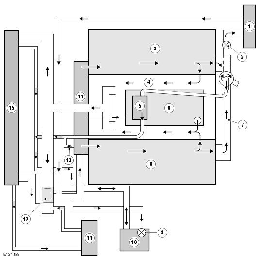
| Item Number | Description |
|---|---|
| 1 | Heater system |
| 2 | Bleed screw |
| 3 | RH cylinder head |
| 4 | Cylinder block |
| 5 | Throttle |
| 6 | Engine oil cooler |
| 7 | Heater manifold |
| 8 | LH cylinder head |
| 9 | Bleed screw |
| 10 | Expansion tank |
| 11 | Transmission fluid cooler |
| 12 | Thermostat |
| 13 | Check valve |
| 14 | Coolant pump |
| 15 | Radiator |
When the engine is running, the coolant is circulated around the engine cooling system by the coolant pump. From the coolant pump, coolant flows through the cylinder heads and the engine oil cooler into the cylinder block and the heater manifold.
In the cylinder block, the coolant flows forwards to the outlet tube. When the coolant is cold, the thermostat is closed and the coolant flows direct from the outlet tube back to the coolant pump. Once the coolant reaches operating temperature the thermostat begins to open, to control system temperature, and coolant flows from the outlet tube to the coolant pump via the radiator. When the thermostat is open, the coolant flow through the radiator also generates a coolant flow through the transmission fluid cooler.
From the heater manifold the coolant flows through the electronic throttle and the heater core, in parallel circuits that are unaffected by the position of the thermostat. From the electronic throttle, the coolant merges with bleed coolant from the coolant pump and flows to the expansion tank. From the heater system, the coolant flows back to the inlet of the coolant pump.
Expansion and contraction of the coolant is accommodated by an air space in the expansion tank and the compliance of the flexible hoses.
If the coolant level in the expansion tank decreases below a predetermined value, the coolant level sensor connects a ground to the central junction box (CJB), which sends a message to the instrument cluster on the medium speed controller area network (CAN) bus to display the message COOLANT LEVEL LOW in the message center. Refer to Information and Message Center .
To control the cooling fan, the engine control module (ECM) sends a pulse width modulation (PWM) signal to the cooling fan drive unit. The engine control module (ECM) varies the duty cycle of the pulse width modulation (PWM) signal between 0 and 100% to vary the clutch engagement and thus fan speed. The engine control module (ECM) determines the required fan speed from:
- Coolant, ambient air and transmission fluid temperatures
- Air conditioning (A/C) system condenser cooling fan demand
- Road speed
- Terrain optimization mode.
If the electrical connections to the viscous fan are disconnected the fan will idle and the engine may overheat. If the engine control module (ECM) detects a cooling fan fault it stores the appropriate diagnostic trouble code (DTC) and signals the instrument cluster on the medium speed controller area network (CAN) bus to display the message COOLING SYSTEM FAULT MONITOR GAUGE in the message center.