Air Bag And Safety Belt PRETENSIONER Supplemental Restraint System (SRS): CLOCKSPRING
| Item Number | Description |
|---|---|
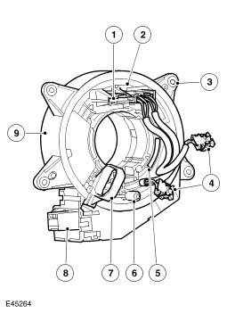
| 1 | Electrical connector for steering wheel switch packs and horn |
| 2 | Inner rotor |
| 3 | Outer housing securing lug |
| 4 | Driver air bag link leads |
| 5 | Viewing window |
| 6 | Drive peg |
| 7 | Stopper |
| 8 | Electrical connector for steering column harness |
| 9 | Outer cover |
The clockspring is installed on the steering column to provide the electrical interface between the fixed wiring harness of the steering column and the components that rotate with the steering wheel, i.e. the driver air bag, the horn and the steering wheel switch packs.
The clockspring consists of a plastic cassette which incorporates an outer cover fixed to the steering column and an inner rotor which turns with the steering wheel. Four securing lugs attach the cover to the multifunction switch on the steering column. The rotor is keyed to the steering wheel by a drive peg. A lug on the underside of the rotor operates the self-cancelling feature of the turn signal indicator switch. A ribbon lead, threaded on rollers in the rotor, links two connectors on the cover to two connectors on the rotor. Link leads for the driver air bag are installed in one of the connectors on the rotor.
To prevent damage to the ribbon lead, both the steering and the clockspring must be centralized when removing and installing the clockspring or the steering wheel. The clockspring is centralized when the drive peg is at six o'clock and 50 - 100% of a yellow wheel is visible in the viewing window.
Replacement clocksprings are fitted with a stopper, which locks the cover to the rotor, in the central position. The stopper must be broken off when the replacement clockspring is installed.