Control Diagram
NOTE:
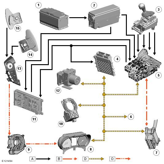
A = Hardwired; B = K bus; D = High speed controller area network (CAN) bus O = local interconnect network (LIN) bus.
| Item Number | Description |
|---|---|
| 1 | Battery |
| 2 | EJB (engine junction box) |
| 3 | Selector lever |
| 4 | ECM (engine control module) |
| 5 | TCM |
| 6 | To other systems |
| 7 | Diagnostic socket |
| 8 | Instrument cluster |
| 9 | Clockspring |
| 10 | Steering angle sensor |
| 11 | CJB (central junction box) |
| 12 | ABS module |
| 13 | Steering wheel LH switchpack |
| 14 | Upshift paddle switch |
| 15 | Downshift paddle switch |