Front HALFSHAFT LH: Removal
CAUTION:
Do not store or install halfshafts with joints at maximum articulation or damage may occur to the joint.
CAUTION:
Do not allow halfshafts to hang unsupported at one end or joint damage will occur.
CAUTION:
Angularly Adjusted Roller (AAR) joints, used at the inboard end of some halfshafts have no internal retaining mechanism and can separate.
- Raise and support the vehicle.
- Drain the differential lubricant. Refer to Differential Draining and Filling article.
- Remove the wheel and tire.
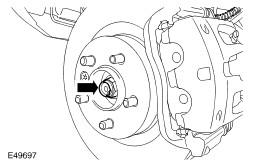
- Remove the halfshaft retaining nut.
- Discard the nut.
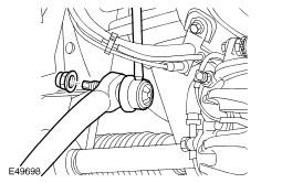
- Disconnect the RH stabilizer bar link.
- Remove and discard the nut.
- Remove the stabilizer bar link nut.
- Remove and discard the nut.
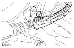
- Release the brake hose bracket from the wheel knuckle.
- Remove the bolt.
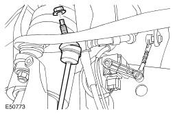
- Loosen the tie-rod end ball joint retaining nut.
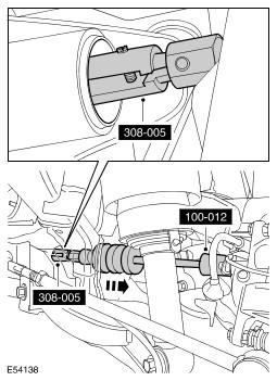
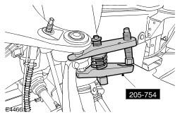
- Using the special tool, release the tie-rod end ball joint from the wheel knuckle.
- Discard the nut.
- Loosen the upper arm retaining nut.
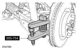
- Using the special tool, release the upper arm ball joint.
- Remove and discard the retaining nut.
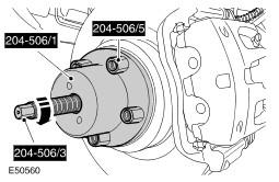
- Using the special tools, release the halfshaft from the wheel hub.
- Release the halfshaft from the wheel knuckle.
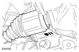
- Release the halfshaft from the differential housing.
- Remove the halfshaft.
- Raise the stabilizer bar to allow removal of the halfshaft.
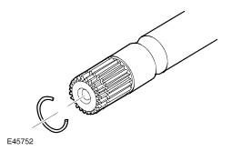
- Remove and discard the snap ring.
- Using the special tools, remove and discard the halfshaft oil seal.
WARNING:
Do not work on or under a vehicle supported only by a jack. Always support the vehicle on safety stands.
CAUTION:
Use a wrench on the hexagon provided to prevent the ball joint rotating.
CAUTION:
Use a wrench on the hexagon provided to prevent the ball joint rotating.
CAUTION:
Make sure the ball joint seal is not damaged. A damaged seal will lead to the premature failure of the joint.
CAUTION:
To prevent the wheel knuckle falling outwards and disconnection of the halfshaft inner joint, support the wheel knuckle.
CAUTION:
Make sure the ball joint seal is not damaged. A damaged seal will lead to the premature failure of the joint.
CAUTION:
The lower arm ball joint can be damaged by excessive articulation. The wheel knuckle must be fully supported at all times. Do not allow the wheel knuckle to hang on the lower arm. Failure to follow this instruction will result in damage to vehicle.
CAUTION:
Do not use a hammer to detach the halfshaft from the hub assembly, failure to follow this instruction may result in damage to the halfshaft.