Wheel Knuckle: Removal
NOTE:
Some variation in the illustrations may occur, but the essential information is always correct.
- Raise and support the vehicle.
- Remove the wheel and tire.
- Loosen the halfshaft retaining nut.
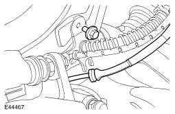
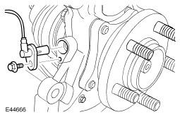
- Release the brake hose bracket from the wheel knuckle.
- Remove the bolt.
- Release the wheel speed sensor from the wheel knuckle.
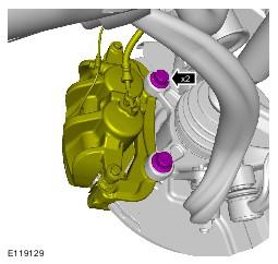
- Remove the bolt.
- Remove the brake caliper and anchor plate.
- Remove the 2 bolts.
- Tie the brake caliper and brake caliper anchor plate assembly aside.
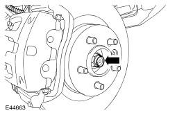
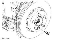
- Remove the brake disc.
- Remove the Torx screw.
- Remove the halfshaft retaining nut.
- Discard the nut.
- Loosen the tie-rod end ball joint retaining nut.
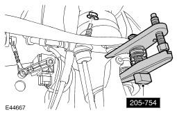
- Using the special tool, release the tie-rod end ball joint from the wheel knuckle.
- Discard the nut.
- Remove and discard the stabilizer bar link nut.
- Loosen the upper arm retaining nut.
- Using the special tool, release the upper arm ball joint.
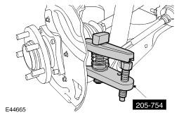
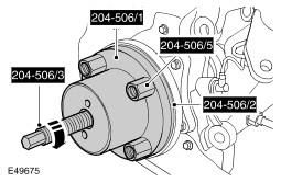
- Using the special tools, release the halfshaft from the drive flange.
- Remove the lower ball joint retaining nut.
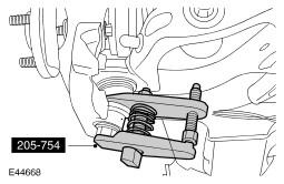
- Using the special tool, release the lower ball joint from the steering knuckle.
- Remove the upper arm retaining nut.
- Discard the nut.
- Remove the wheel knuckle.
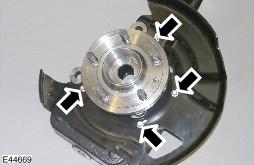
- Remove the brake disc dust shield.
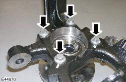
- Remove the four retaining bolts.
- Remove the wheel hub.
- Remove the 4 bolts.
WARNING:
Do not work on or under a vehicle supported only by a jack. Always support the vehicle on safety stands.
CAUTION:
Do not allow the brake caliper to hang on the brake hose.
CAUTION:
LH side: Do not allow the brake caliper to hang on the brake pad wear warning sensor lead.
CAUTION:
Use a wrench on the hexagon provided to prevent the ball joint rotating.
CAUTION:
Do not use a hammer to detach the halfshaft from the hub assembly, failure to follow this instruction may result in damage to the halfshaft.
CAUTION:
The lower arm ball joint can be damaged by excessive articulation. The wheel knuckle must be fully supported at all times. Do not allow the wheel knuckle to hang on the lower arm. Failure to follow this instruction will result in damage to vehicle.
NOTE:
Do not disassemble further if the component is removed for access only.