Lower Arm Bushing: Removal
NOTE:
The bushings must be replaced in pairs, LH and RH sides.
NOTE:
Take note of the fitted position of the bush.
- Make sure that the tire pressures are correct and that the vehicle is at the correct ride height. Refer to Ride Height Adjustments article.
- Mark the position of the bushing in relation to the lower arm.
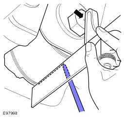
- Using a spirit level type engineers square, align through the center of the bolt head retaining the lower arm rear bush with a perpendicular drop.
- Align the rule of the engineers square along the lowest point on the circumference of the lower arm rear bush boss.
- Apply a piece of tape to the arm and mark a horizontal line along the underside of the lower arm rear bush boss (parallel with the bush axis).
- Make sure that the process is carried out on both right-hand side and left-hand side.
- Raise and support the vehicle.
- Remove the wheels and tires.
- Remove the RH lower arm. See Lower Arm .
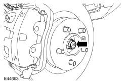
- Remove the halfshaft retaining nut.
- Discard the nut.
- Disconnect the LH stabilizer bar link.
- Remove and discard the nut.
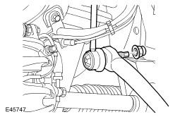
- Release the brake hose bracket from the wheel knuckle.
- Remove the bolt.
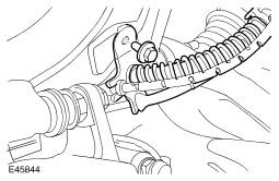
- Loosen the tie-rod end ball joint retaining nut.
- Using the special tool, release the tie-rod end ball joint from the wheel knuckle.
- Discard the nut.
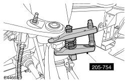
- Loosen the upper arm retaining nut.
- Using the special tool, release the upper arm ball joint.
- Remove and discard the retaining nut.
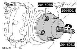
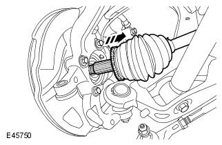
- Using the special tools, release the halfshaft from the wheel hub.
- Release the halfshaft from the wheel knuckle.
- Secure the halfshaft clear of the lower arm.
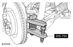
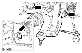
- Remove the lower ball joint retaining nut.
- Using the special tool, release the lower ball joint from the steering knuckle.
- Loosen the 2 lower arm bolts.
- Mark the position of the bolts in relation to the chassis brackets.
- Disconnect the shock absorber and spring assembly from the lower arm.
- Remove the LH retaining bolt.
- Remove the LH lower arm.
- Note the position of the bushing in relation to the lower arm.
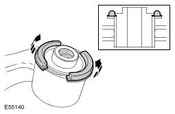
- Remove the lower arm front bushing flanges.
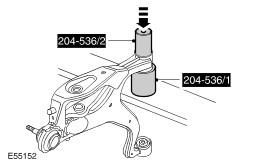
- Using the special tools, remove and discard the lower arm front bushings.
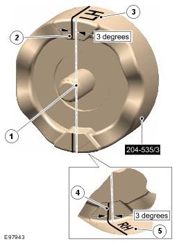
- Apply alignment guide lines to installer tool (204-535/3).
- Mark center line on installer tool.
- Mark line across top surface 3 degrees to the left of center line.
- Mark 'LH' on top surface.
- Mark line across bottom surface 3 degrees to the left of the center line.
- Mark 'RH' on bottom surface.
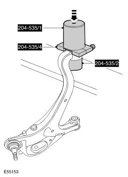
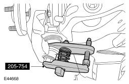
- Using the special tools, remove and discard the lower arm rear bushings.
WARNING:
Do not work on or under a vehicle supported only by a jack. Always support the vehicle on safety stands.
CAUTION:
Use a wrench on the hexagon provided to prevent the ball joint rotating.
CAUTION:
Make sure the ball joint seal is not damaged. A damaged seal will lead to the premature failure of the joint.
CAUTION:
To prevent the wheel knuckle falling outwards and disconnection of the halfshaft inner joint, support the wheel knuckle.
CAUTION:
Make sure the ball joint seal is not damaged. A damaged seal will lead to the premature failure of the joint
CAUTION:
Do not use a hammer to detach the halfshaft from the hub assembly, failure to follow this instruction may result in damage to the halfshaft.
CAUTION:
The bush flanges need to be removed to allow bush removal.