Vehicle Dynamic Suspension: General
Front suspension is detailed in a separate section. Refer to Front Suspension article.
Rear suspension is detailed in a separate section. Refer to Rear Suspension article.
Terrain Response™ is detailed in a separate section. Refer to Ride and Handling Optimization article.
The dynamic suspension system is a four corner air suspension system which is fitted to higher specification vehicles in place of the conventional damper and coil spring suspension used on non-air suspension models.
The dynamic suspension system is electronically controlled by an air suspension control module which controls the air supply unit, reacts to inputs from four height sensors and distributes air around the system via valve blocks.
The main air suspension system components are:
- Air suspension control module
- Air supply unit
- Four height sensors
- Three valve block assemblies
- Reservoir
- Air harness
- Four suspension air spring damper modules.
The four corner air suspension system maintains the vehicle height under all operating conditions by controlling the mass of air in the air springs. The air suspension control module uses signals from the four height sensors to maintain the correct suspension height. This is achieved by operating pneumatic control valves to increase or decrease the mass of air in the air spring damper modules.
The air suspension system has three driver selectable, pre-determined ride heights. A driver interface indicates the selected ride height and direction of movement. Additional information is also relayed to the driver via the instrument cluster message center (where fitted) and by audible warnings also transmitted by the instrument cluster.
Height changes can only be made when the engine is running and the driver's and passenger doors are closed.
Access height can be selected with the engine not running, within 40 seconds of moving the ignition switch to the off position provided the driver's door has not been opened in this time.
The air suspension can be controlled manually by the driver using a switch on the center console to select the required height change.
Schematic Pneumatic Circuit
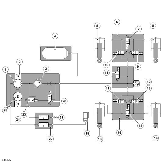
| Item Number | Description |
|---|---|
| 1 | Compressor |
| 2 | Compressor temperature sensor |
| 3 | Air dryer |
| 4 | Reservoir |
| 5 | Front LH air spring damper module |
| 6 | Front valve block |
| 7 | Cross link valve |
| 8 | Front RH air spring damper module |
| 9 | Front RH corner valve |
| 10 | Front LH corner valve |
| 11 | Reservoir control valve |
| 12 | Pressure sensor |
| 13 | Rear RH corner valve |
| 14 | Rear RH air spring damper module |
| 15 | Cross link valve |
| 16 | Rear valve block |
| 17 | Rear LH corner valve |
| 18 | Rear LH air spring damper module |
| 19 | Inlet air filter |
| 20 | Pilot exhaust valve |
| 21 | Exhaust |
| 22 | Air silencer |
| 23 | Pressure relief and exhaust valve |
| 24 | Motor temperature sensor |
| 25 | Electric motor |