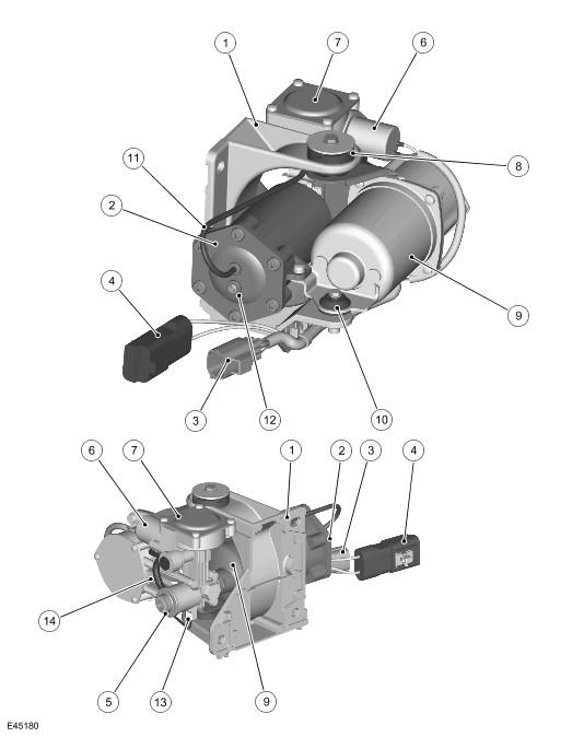
Air Supply Unit: Notes
| Item Number | Description |
|---|---|
| 1 | Mounting bracket |
| 2 | Air dryer |
| 3 | Pilot exhaust valve solenoid and temperature sensors harness connector |
| 4 | Motor harness connector |
| 5 | Intake port |
| 6 | Pilot exhaust valve |
| 7 | Exhaust valve |
| 8 | Isolation mounting rubber (2 off) |
| 9 | Electric motor |
| 10 | Isolation mounting rubber (1 off) |
| 11 | Pilot air pipe |
| 12 | High pressure supply to air suspension system |
| 13 | Compressor cylinder head temperature sensor |
| 14 | Compressor |
The air supply unit is located on the outside of the left hand chassis rail, forward of the upper control arm. The unit is attached to the chassis rail with three bolts and is protected by an acoustic box.
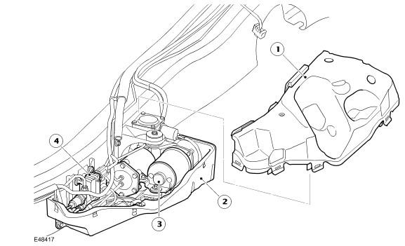
Acoustic Box
| Item Number | Description |
|---|---|
| 1 | Upper cover |
| 2 | Lower cover |
| 3 | Air supply unit |
| 4 | Reservoir valve block |
The acoustic box, which comprises of two parts; upper and lower, surrounds the air supply unit. The acoustic box is a plastic molding which is lined with an insulating foam which controls the operating noise of the air supply unit. The reservoir valve block is also located in the acoustic box, forward of the air supply unit.
The air supply unit comprises the following major components:
- A piston compressor
- A 12V electric motor
- A solenoid operated pilot valve
- An exhaust valve
- An air dryer unit
The air supply unit can be serviced in the event of component failure, but is limited to the following components; air dryer, pilot exhaust pipe and the rubber mounts.
The air supply unit is attached to a bracket which is bolted to the chassis. The unit is mounted to the bracket with flexible isolation mounting rubbers which assist with preventing operating noise being transmitted to the chassis.
Removal of the air supply unit does not require the whole air suspension system to be depressurized. The front and rear valve blocks and the reservoir valve block are normally closed when de-energized, preventing air pressure in the air springs and the reservoir escaping when the unit is disconnected.
There are a number of conditions that will inhibit operation of the air supply unit. It is vitally important that these system inhibits are not confused with a system malfunction. A full list of air supply unit inhibits are given in the air suspension control module section in this chapter.
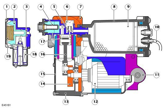
Air Supply Unit - Sectional View
| Item Number | Description |
|---|---|
| 1 | Exhaust valve cap |
| 2 | Plunger |
| 3 | Valve seat |
| 4 | Intake silencer port |
| 5 | Delivery valve |
| 6 | Valve guide |
| 7 | Cylinder head |
| 8 | Dryer case |
| 9 | Desiccant |
| 10 | Pilot exhaust line |
| 11 | Isolation rubber mount |
| 12 | Motor assembly |
| 13 | Crankcase |
| 14 | Crank |
| 15 | Crankcase cover |
| 16 | Connecting rod |
| 17 | Piston |
| 18 | Pilot exhaust valve |
| 19 | Spring - pressure relief |