Control Diagram
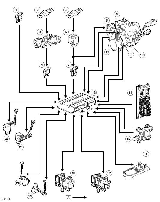
| Item Number | Description |
|---|---|
| 1 | Fuse 26E (20A) |
| 2 | Fusible link 11E (30A) |
| 3 | Ignition switch |
| 4 | Fuse 35P (5A) |
| 5 | Fusible link 10E (60A) |
| 6 | Air supply unit relay |
| 7 | Fuse 3E (5A) |
| 8 | Air supply unit |
| 9 | Compressor temperature sensor |
| 10 | Motor |
| 11 | Motor temperature sensor |
| 12 | Exhaust valve solenoid |
| 13 | Air suspension control module |
| 14 | Central junction box |
| 15 | Reservoir control valve |
| 16 | Air suspension switch |
| 17 | Front control valve |
| 18 | Rear control valve |
| 19 | RH rear height sensor |
| 20 | LH rear height sensor |
| 21 | RH front height sensor |
| 22 | LH front height sensor |
NOTE:
A
= Hardwired