Front Air Shock Absorber: Installation
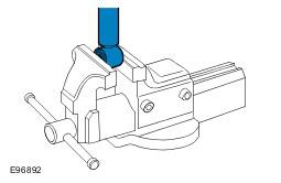
- Position the front shock absorber and air spring assembly in a vice.
- Clean the components.
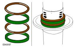
- Lift the seal carrier to expose the O-ring seal stack.
- Make sure that the damper body O-ring seals and spacers are fully seated to the spring seat.
- Install new O-ring seals to the seal carrier.
- Apply Loctite 8021 (silicon-based oil) to the O-ring seals.
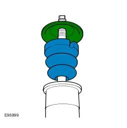
- Install the bump plate and spring aid.
- Install the air spring.
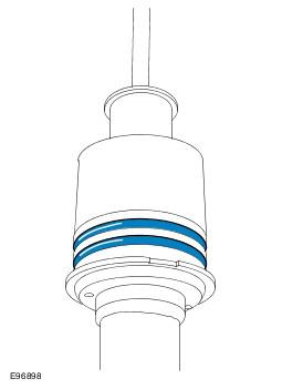
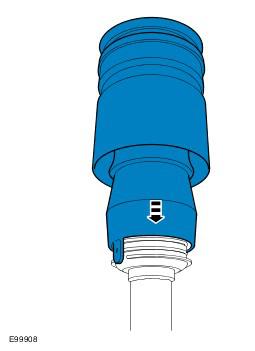
- Align the sleeve support with the first O-ring seal making sure that the location tag is correctly aligned with the spring seat cut-out.
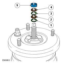
- Install the components in the following order:
- O-ring seal
- Spacer
- O-ring seal
- Spacer
- Spacer
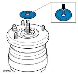
- Install the rebound washer.
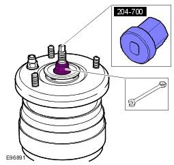
- Install a new nut and using the special tool, and tighten to 98 Nm (72 lb.ft).
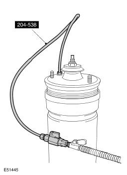
- Using the special tool coupled to a tire inflator with a gauge, apply approximately 2 bar of air pressure to the air spring to fully seat the sleeve support over the O-ring seals.
- Check the assembly for leaks.
- Inflate the module to 4 bar and check for pressure loss using leak detector spray.
- If a leak is suspected, immerse the shock absorber and air spring assembly in a tank of water to locate the source of the leak.
- Depressurize and remove the special tool from the shock absorber and air spring assembly.
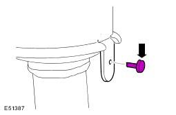
- Install the nylon retaining pin.
- Install the front shock absorber and air spring assembly. See Front Shock Absorber and Air Spring Assembly . .
CAUTION:
Make sure protective jaws are installed to the vice. Failure to follow this instruction may result in damage to the component.
CAUTION:
Do not clamp the shock absorber tube. Failure to follow this instruction may result in damage to the component.
CAUTION:
Use compressed air and lint free non-flocking material.
CAUTION:
Take care not to damage the O-ring seals during installation.
NOTE:
Make sure that these components are installed to the noted removal position.
CAUTION:
Make sure that the threads of the front air shock absorber are covered with protective tape.
CAUTION:
Take care not to damage the O-ring seals during installation.
NOTE:
The "T5" stamp on the upper face of the rebound washer must be visable after assembly.
CAUTION:
The air supply must be free of any moisture.
CAUTION:
If during disassembly the air sleeve is unrolled, the air sleeve may inflate incorrectly (to one side). If this occurs, release the air pressure, and insert a suitable tool that will not damage the air sleeve or piston (a screw driver handle), into the side opposite the bulge. Inflate and deflate until the air sleeve inflates correctly (the air sleeve will be uniform inside the shroud).
NOTE:
To prevent damage when seating the sleeve support over the large black O-rings, compressed air should be used to inflate the air spring.
NOTE:
Install a new air spring pipe connector.