DMTL Operation
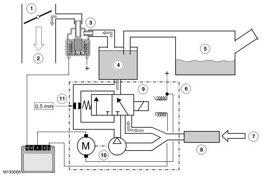
To check the fuel tank and the evaporative emission (EVAP) system for leaks, the engine control module (ECM) operates the DMTL pump and monitors the current draw. Initially, the engine control module (ECM) establishes a reference current by pumping air through the reference orifice and back to atmosphere. Once the reference current is determined, the engine control module (ECM) closes the change-over valve, which seals the evaporative emission (EVAP) system. The purge valve remains de-energized and is therefore closed. The output from the air pump is diverted from the reference orifice and into the evaporative emission (EVAP) system.
DMTL System Inactive
| Item Number | Description |
|---|---|
| 1 | Throttle plate |
| 2 | Air flow to engine |
| 3 | Purge valve |
| 4 | Charcoal canister |
| 5 | Fuel tank |
| 6 | DMTL pump assembly |
| 7 | Air intake |
| 8 | Air filter |
| 9 | Change-over valve |
| 10 | Pump |
| 11 | Reference orifice |
In its inactive state, the DMTL pump motor and the change-over valve solenoid are not energized. When the engine control module (ECM) energizes the purge valve, filtered fresh air enters the evaporative system through the open change-over valve of the DMTL pump. The filtered air enters the system compensating for engine vacuum drawing on the hydrocarbon vapors stored in the charcoal canister.
DMTL System Active
Phase 1 - Reference Measurement

| Item Number | Description |
|---|---|
| 1 | Throttle plate |
| 2 | Air flow to engine |
| 3 | Purge valve |
| 4 | Charcoal canister |
| 5 | Fuel tank |
| 6 | DMTL pump assembly |
| 7 | Air intake |
| 8 | Air filter |
| 9 | Change-over valve |
| 10 | Pump |
| 11 | Reference orifice |
When the engine control module (ECM) activates the DMTL system, it first activates only the DMTL pump motor. This pumps air through a 0.5 mm (0.02 in) reference orifice, which causes the electric motor to draw a specific amperage value. This value equates to the size of the reference orifice.
Phase 2 - Leak Detection

| Item Number | Description |
|---|---|
| 1 | Throttle plate |
| 2 | Air flow to engine |
| 3 | Purge valve |
| 4 | Charcoal canister |
| 5 | Fuel tank |
| 6 | DMTL pump assembly |
| 7 | Air intake |
| 8 | Air filter |
| 9 | Change-over valve |
| 10 | Pump |
| 11 | Reference orifice |
When the change-over valve solenoid is energized, the valve closes, sealing the evaporative emission (EVAP) system from atmosphere. Providing there are no leaks, the air pump will begin to pressurize the evaporative emission (EVAP) system and the load and current draw on the pump increases. By monitoring the rate and level of the current increase, the engine control module (ECM) can determine if there is a leak in the evaporative emission (EVAP) system.
During normal vehicle operation, the engine control module (ECM) energizes the heating element in the pump to prevent condensation formation and possible incorrect current readings.
Leaks are classified as:
- Minor - equivalent to a hole diameter of 0.5 to 1.0 mm (0.02 to 0.04 in)
- Major - equivalent to hole diameter of 1.0 mm (0.04 in) or greater.
The engine control module (ECM) performs a check for major leaks each time the ignition is switched off, providing the following conditions are met:
- The vehicle speed is zero
- The engine speed is zero
- The atmospheric pressure is above 70 kPa (10.15 lbf/in2 ), i.e. the altitude is less than approximately 3047 m (10000 feet)
- The ambient temperature is between 0 and 40 °C (32 and 104 °F)
- The charcoal canister vapor concentration factor is 5 or less (where 0 is no fuel vapor, 1 is stoichiometric fuel vapor and greater than 1 is rich fuel vapor)
- The fuel tank level is valid and between 15 and 85% of nominal capacity
- The engine running time during the previous cycle was more than 10 minutes
- The battery voltage is between 10 and 15 volts
- The last engine off time was more than 180 minutes
- No errors are detected with the evaporative emission (EVAP) components, the ambient air temperature and the fuel level
- High range is selected on the transfer box.
The engine control module (ECM) performs a check for minor leaks after every 2nd major leak check.
When the leak check is complete, the engine control module (ECM) stops the DMTL pump and opens (de-energizes) the change-over valve.
If the fuel filler cap is opened or refueling is detected during the leak check, by a sudden drop in the current draw or a rise in the fuel level, the engine control module (ECM) aborts the leak check.
If a leak is detected during the check, the engine control module (ECM) stores an appropriate fault code in its memory. If a leak is detected on two consecutive checks, the engine control module (ECM) illuminates the malfunction indicator lamp (MIL) in the instrument cluster on the next drive cycle.
The duration of a leak check can be between 60 and 900 seconds depending on the test results (developed tank pressure amperage within a specific time period) and fuel tank level.
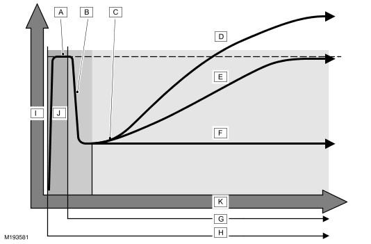
The following chart depicts the logic used to determine fuel system leaks:
Test Results
| Item Number | Description |
|---|---|
| A | Current stabilizes |
| B | Current drops |
| C | Current rises |
| D | No leak detected |
| E | 0.5 mm leak |
| F | Leak >1.0 mm |
| G | Change-over valve energized |
| H | Pump motor energized |
| I | Motor current pressure |
| J | Reference measurement 0.5 mm |
| K | Time duration |