Intake Manifold
| Item Number | Description |
|---|---|
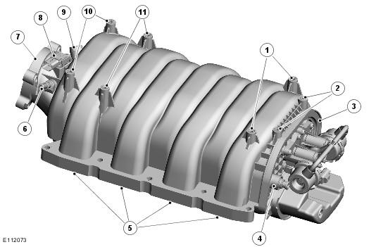
| 1 | Engine cover rear attachment points |
| 2 | Engine harness shield attachment points |
| 3 | Cover plate |
| 4 | Brake booster vacuum connection |
| 5 | Outlet ports |
| 6 | Evaporative emissions connection |
| 7 | Inlet port |
| 8 | MAP (manifold absolute pressure) sensor |
| 9 | Part load breather connection |
| 10 | Fuel crossover tube attachment points |
| 11 | Engine cover front attachment points |
The intake manifold is installed between the cylinder heads and directs air from the electric throttle to the individual cylinders. The inlet port connects to a central chamber in the intake manifold. Eight separate tracts connect the central chamber to the outlet ports. A cover plate seals the rear of the intake manifold.
The intake manifold incorporates:
- A stub pipe for connection of the part load breather.
- A stub pipe for connection of the evaporative emissions system.
- A manifold absolute pressure (MAP) sensor.
- A vacuum connection for the brake booster.
- Threaded inserts to provide attachment points for the electric throttle, fuel crossover tube, engine cover and an engine harness shield.
- Compression limiters in the cylinder head attachment points.
- Seals in the inlet and outlet ports.
- A VIS (variable intake system).
Variable Intake System
| Item Number | Description |
|---|---|
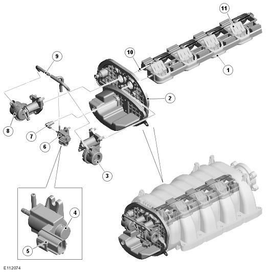
| 1 | Cassette |
| 2 | Cover plate |
| 3 | RH pneumatic actuator |
| 4 | Vent cap |
| 5 | Electrical connector |
| 6 | Tuning valve |
| 7 | Vacuum connector |
| 8 | LH pneumatic actuator |
| 9 | Vacuum hoses |
| 10 | Drive shaft |
| 11 | Flap valve |
The VIS changes the length of the tracts in the intake manifold to improve the air flow to the cylinders, which improves the engine power and torque.
A cassette in the intake manifold contains eight flap valves, each located in an opening part-way along one of the tracts. Two drive shafts connect the flap valves together in two groups of four. Each drive shaft is connected to a pneumatic actuator installed on the cover plate of the intake manifold.
A tuning valve, also installed on the cover plate, controls the application of vacuum pressure to the pneumatic actuators. The tuning valve is a normally-closed solenoid-operated valve installed in the vacuum line between the cover plate and the pneumatic actuators. A vent cap on the tuning valve allows atmospheric pressure into the vacuum line to the pneumatic actuators when the tuning valve is closed.
The engine control module (ECM) controls the operation of the tuning valve.