Sensor Operating Principle
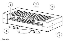
| Item Number | Description |
|---|---|
| 1 | Magnetic foil |
| 2 | Spacer |
| 3 | Ceramic surface |
| 4 | Magnet |
| 5 | Resistance film |
The film resistors are arranged in a linear arc with resistance ranging from 51.2 to 992.11 Ohms. The electrical output signal output is proportional to the amount of fuel in each side of the tank and the position of the float arms. The measured resistance is processed by the instrument cluster to implement an anti-slosh function. This monitors the signal and updates the fuel gauge pointer position at regular intervals, preventing constant pointer movement caused by fuel movement in the tank due to cornering or braking.
A warning indicator is incorporated in the instrument cluster and illuminates when the fuel level is at or below 10 liters (2.64 US gallons).
The fuel level sender signals are converted into a CAN bus message by the instrument cluster as a direct interpretation of the fuel tank contents in liters. The ECM uses the CAN bus message to store additional On-Board Diagnostic (OBD) P Codes for misfire detection when the fuel level is below a predetermined capacity.